The first order of business is getting the car
up, rear wheels off and easy access to the rear end.
To do this, I borrowed four 4'X4" posts from my neighbour, jacked up the
car and placed these under my floor rails.
I won't go into the details however, I did have two floor jacks and
ramps which helped.
Once the car was up, I checked it for stability with vigorous shaking an then
stuck a floor jack at the front and rear jack points to keep the front and
back from "hanging stress"

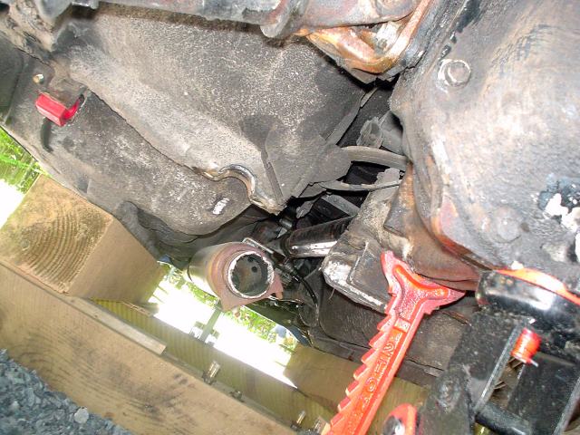
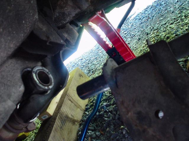
Here is a pic showing the car rails resting on the 4" X4" posts
and the front and back floor jacks supporting the differential and front cross
member.
The next job was to get the exhaust pipe and
muffler out of
the way.
Note that the 4" X 4" posts stop well before the differential mount
to provide "elbow room" and access to the front differential mount.
As well, jack stands are positioned for additional safety.
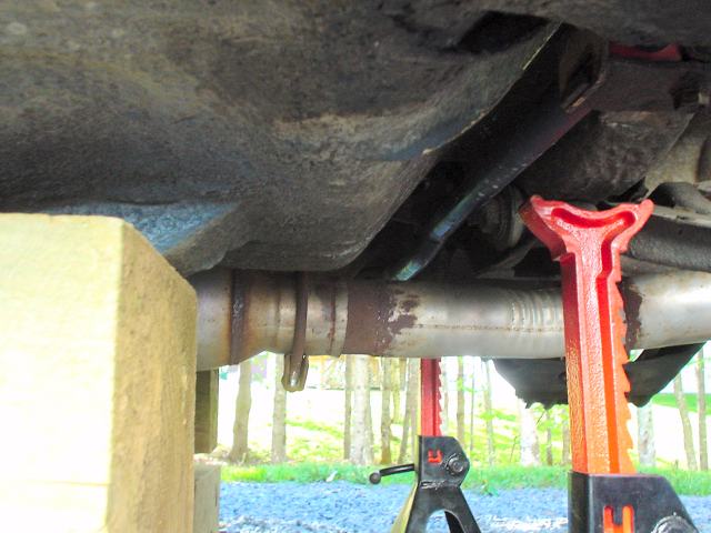
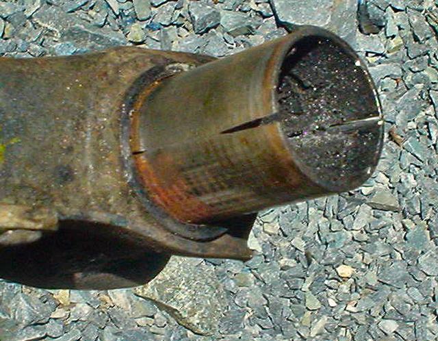
Here is the 2.5" exhaust pipe in the way.

I cut the exhaust with a hand grinder just behind the resonator.
Gone!
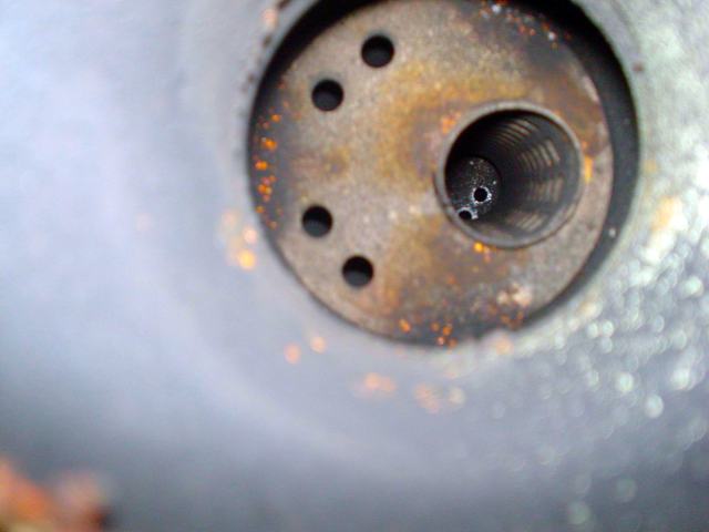
Dang! look at the restriction inside the
resonator.
I thought I lost a lot of power when they put that on!!
It sure cured
the drone but now I'm going to glass pack!
The next order of business is to loosen all of
the suspension bolts.
Grab a 24mm socket and attack the inner control arm bolts

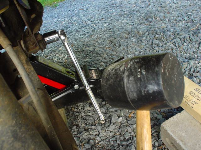
Well you can see I do not have a pipe extension breaker bar (I do now!)
So I used the good old "tap tap tap" with a big rubber mallet while
pushing.
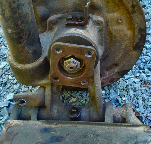
Next, remove the 1/2 shafts at the hub flange
Access from this angle is great.
Two 14mm box/open end wrenches is all you need to do the job.

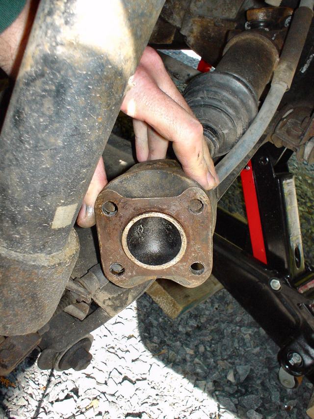
Note the lack of symmetry. The bolts form a rectangle, not a square.

Another view. Note that the 1/2 shaft can be compressed and extended as it
has a degree of freedom along its axis.
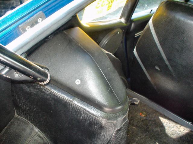
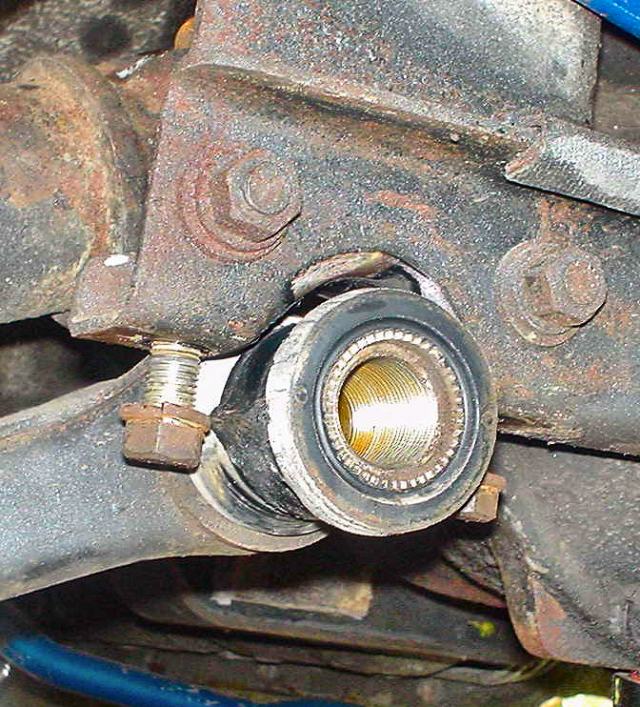
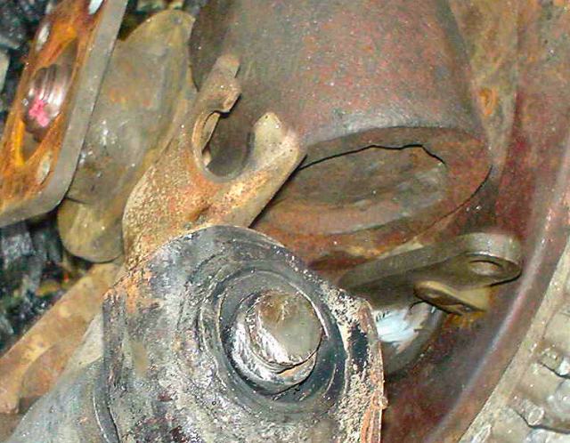
Well the dreaded spindle is ominously waiting
to be tackled but the first "Mr Ugly" you see is the dreaded hub
nut!
Take a look:
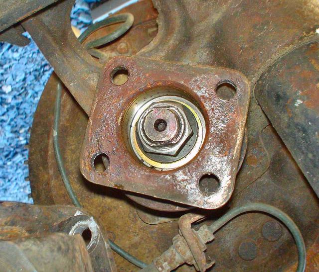
See the staking of the nut against the flat sides of the hub's threaded
spindle.
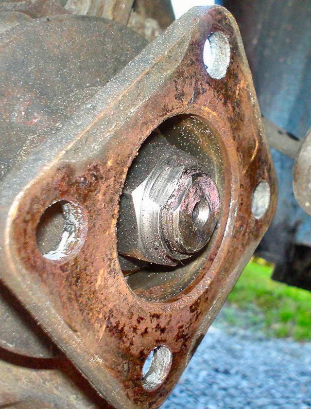
A close-up
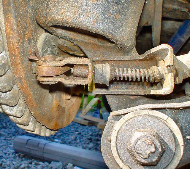
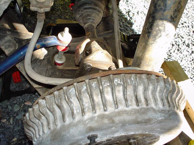
Well, since we are looking around, here is the E-brake mechanism and cable
attachment.
And the end of the spindle pin. Gee how come the spindle pin and hub nut are
so tough and so close!!
I am depressed now!
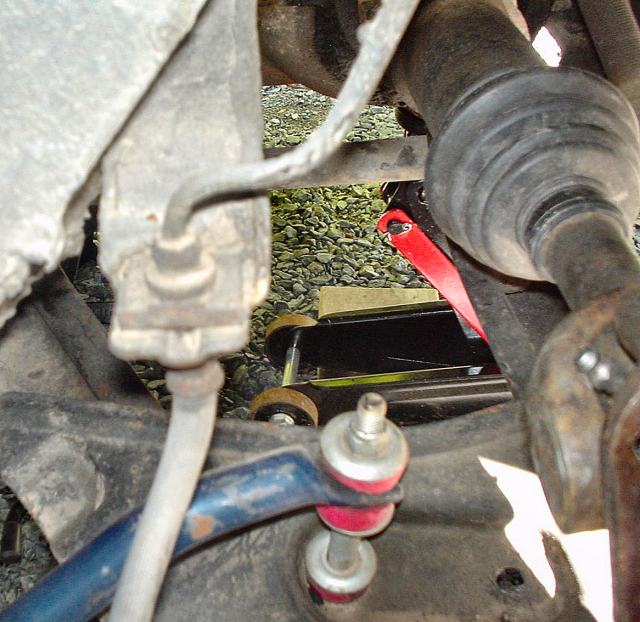
Time to move on. The rear sway bar end-links are easy to remove.
9/16" wrenches for these Suspension Techniques units!
Remind me to switch them to metric!
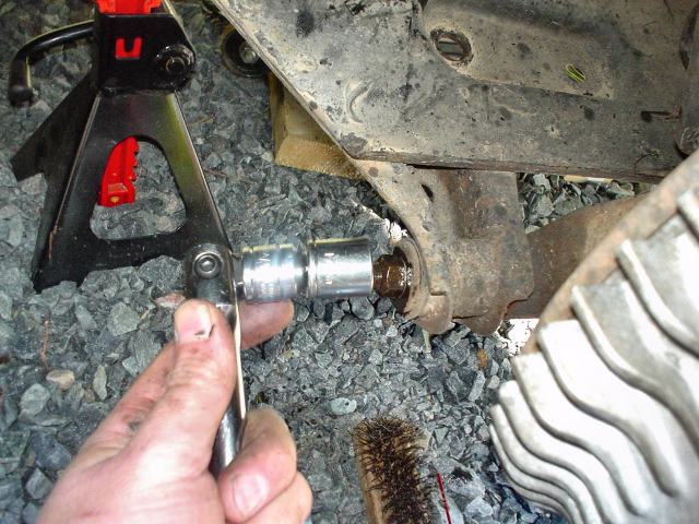
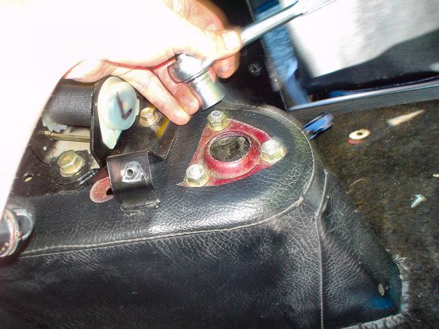
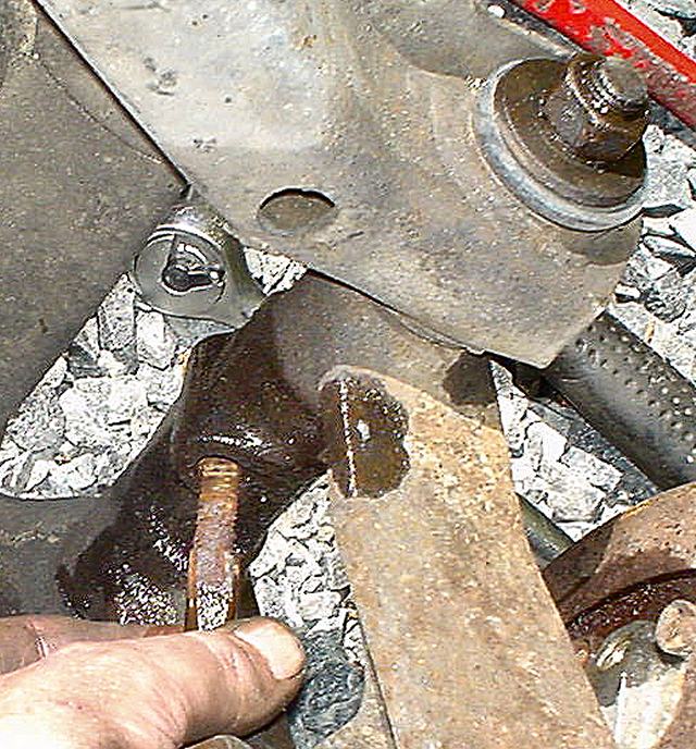
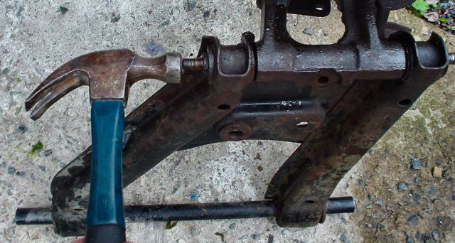
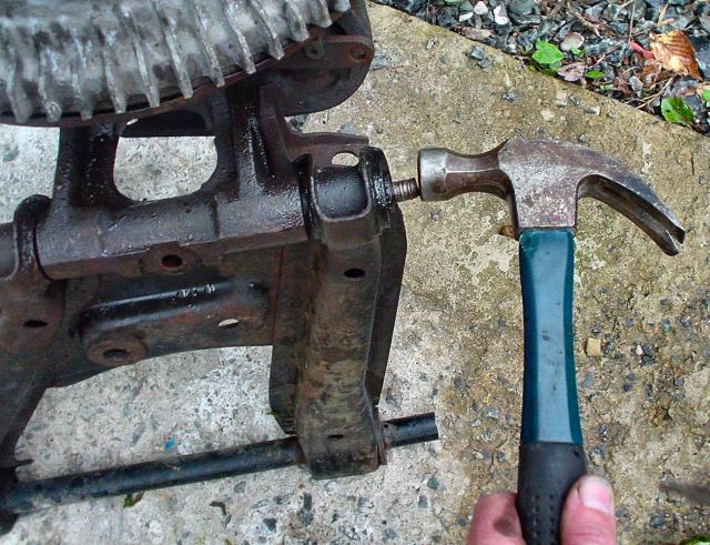
Well now is a good time to crack loose the spindle pin end bolts.
17mm socket
does the trick!
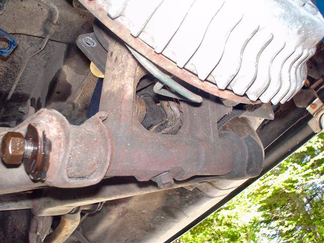
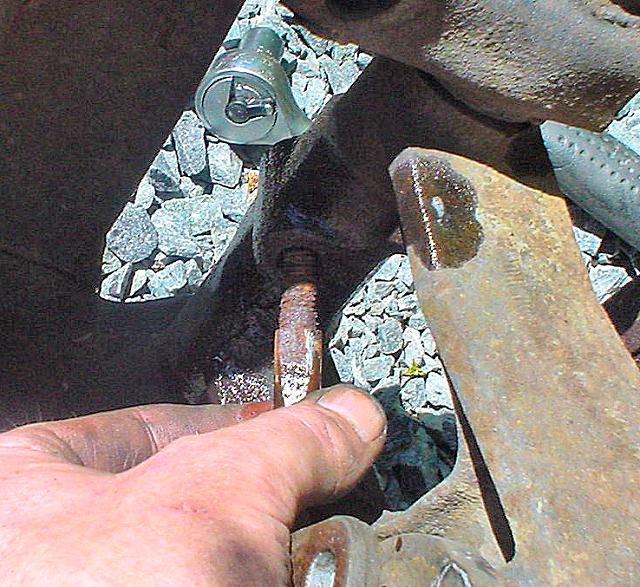
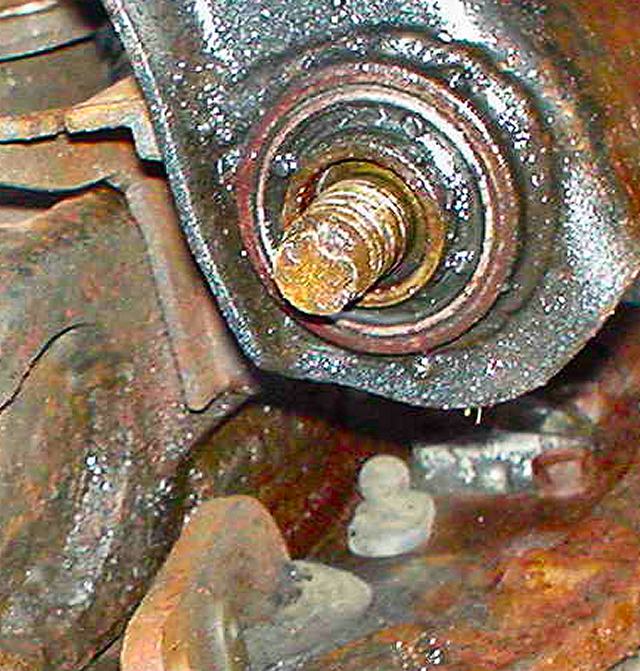
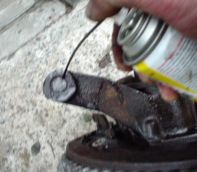
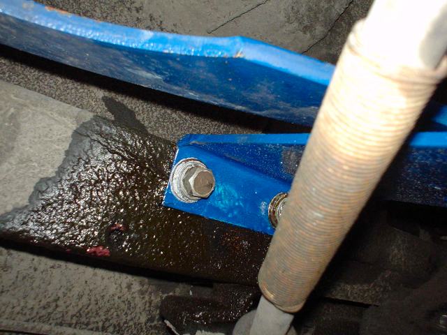
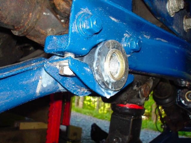
Here is a good look at the bottom of the spindle pin lock bolt (a nut and lock
washer)
This part is typically seized with rust inside.

Spray some penetrating oil and back off the nut just enough to prevent the
threads from being exposed to the hammer.
Firmly tap the nut until the lock pin starts to move up.
Back off the nut and continue tapping the lock pin further up.
Repeat until the lock pin is loose then remove.

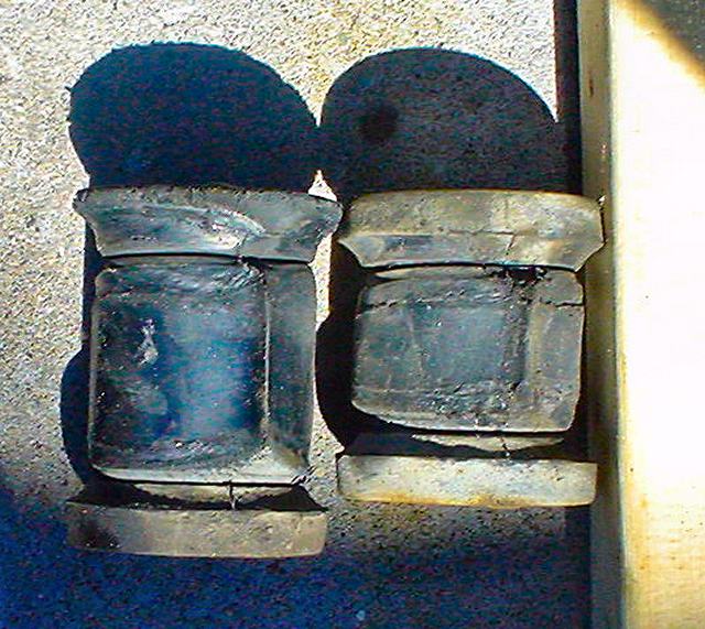
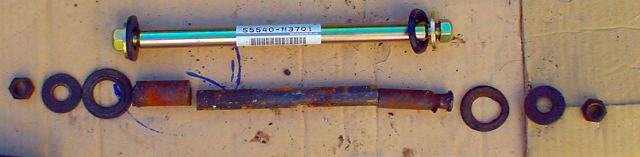
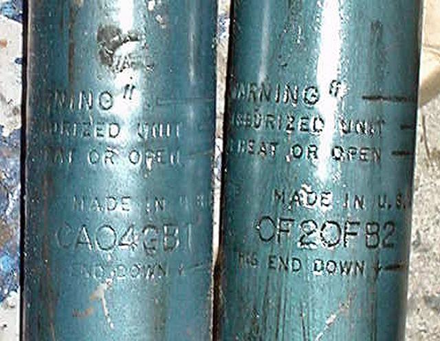
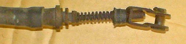
Here is the old vs. new. These pins are from Victoria British.
They are slightly different from the Nissan originals but they work fine.
Time for a break!
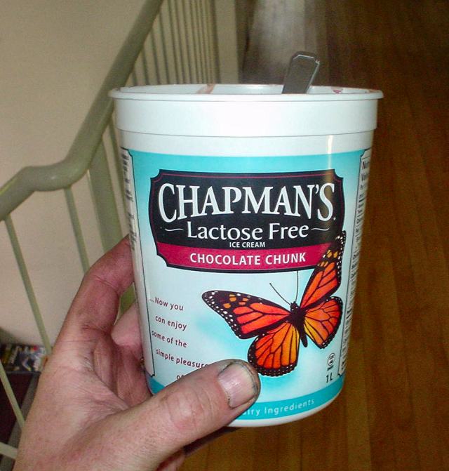
Yum! All gone!
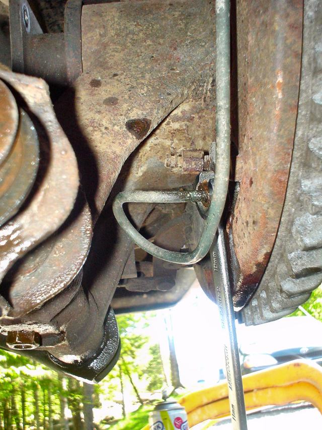
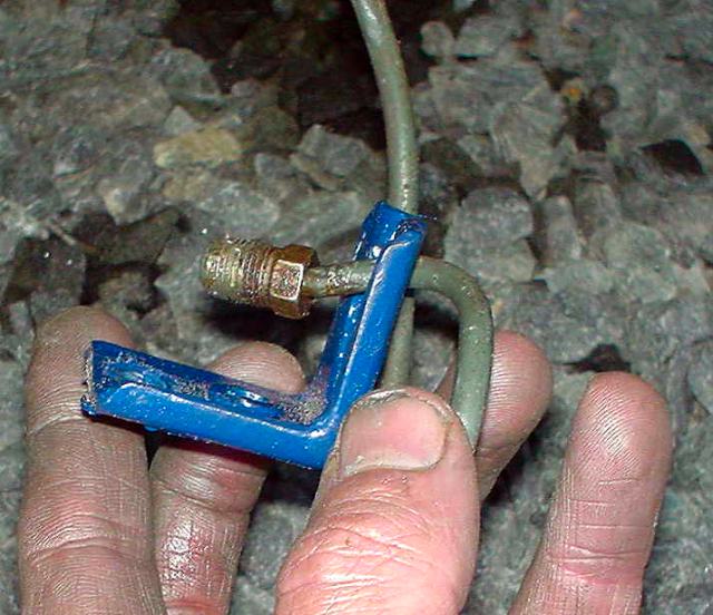
Now to remove the brake line. I chose this point because it seemed easier
however the FSM and an online instruction recommend decoupling at the top of
the wheel.
I too recommend that one! Please forget you saw this! lol!

There is a yummy reason for everything!
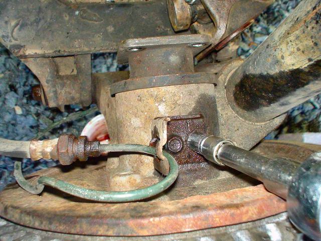
Removing the top brake line bracket.
You can see the coupler I should have separated too!
Yeah I know, they are not stainless steel hoses! Someday!
"Quick, get in the car!"
Loosen the three strut mount nuts and ONLY LOOSEN the center strut nut.
DO NOT REMOVE
ANY OF THESE!
Note: Most hardware takes 14mm, 17mm and 24mm sockets. The rest is 10mm or 12mm.
Ok, now to start removing the control arm AND strut assembly as one unit.
Remove the rear inner control arm bolt
Big sucker ain't it!
Remove the clamping plate.
Note: all nuts and bolts in this pic take a 14mm socket.
Next remove the front inner control arm nut and loosen the front
differential cross member where the bushing passes.
Be sure to support the differential. note the jack
stand under it's neck
Pull out the control arm from the bushing.
If you can't do this then just remove the complete differential cross
member (as long as the differential is supported).
I did not realize that I could do this until later.
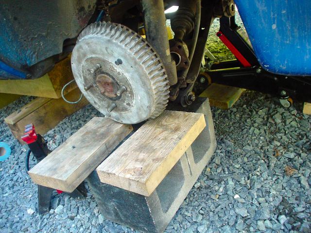
If you are alone, block the assembly so that it does not fall then do a
leaning tower of Pisa into your wheel well!
Back in the car again!
Remove the three strut mounting nuts with a 14mm socket.
Note: THIS WILL ALLOW THE SUSPENSION ASSEMBLY TO DROP.
DO NOT REMOVE
THE CENTER NUT THAT HOLDS THE SPRING AND STRUT ASSEMBLY TOGETHER!
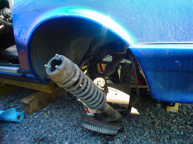
Motorcycle Mama Won't You Lay that Big Spike Down!
Success! Woo Hoo!
Don't look back in anger!
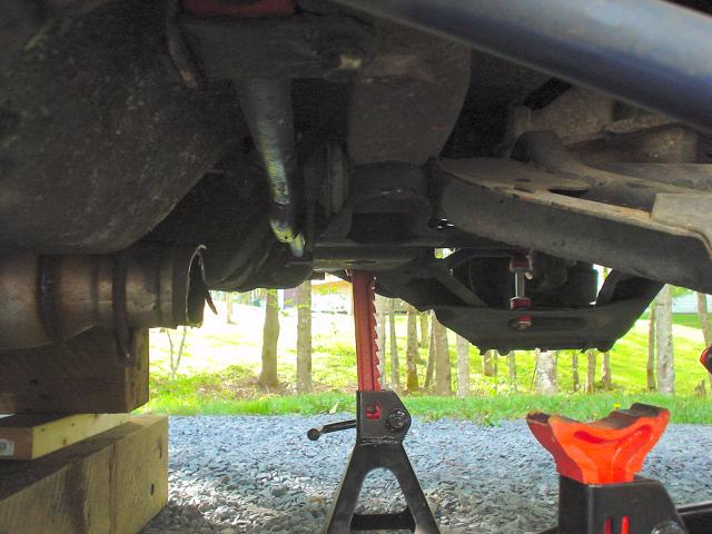
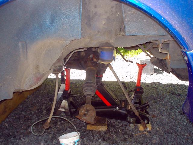
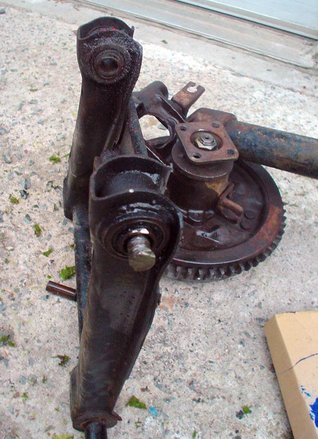
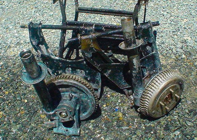
Here is a good pick of the differential supported by the floor jack and jack
stand.
Note that I removed the upright supports too. (They hand from the unibody and
hold the rear control arm and bushings).
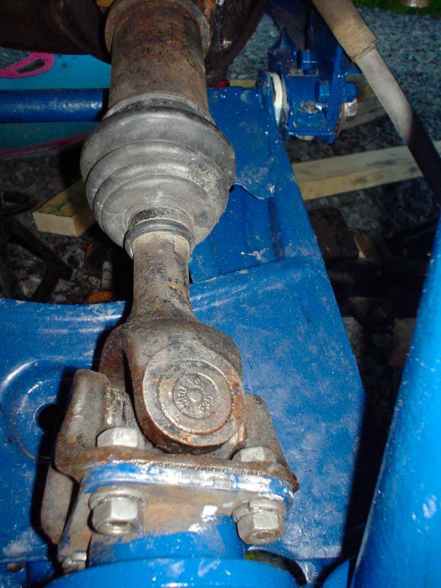
The differential is still attached to the drive shaft and it is also attached
to the moustache bar (I upgraded its bushings last year)
This configuration makes it very easy to access and change the differential
mount! (see below)

Grab and turn a stubborn bushing with a pipe wrench to convince it the
ride has ended!
27 years is a long ride for sure!
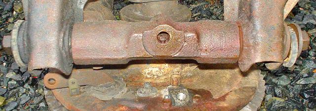
Spindle pin and hub nut in one shot... doom and gloom
Retired! (front and back inner bushings)
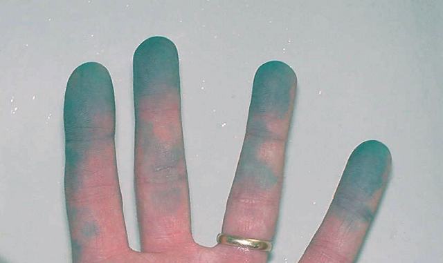
OK, this is a staged shot! I took the lock pin out already... my
fingers are not as strong as the red hand in Kammy's infamous photo!
Anyway, this gives you an idea of the rust and location of the pin.
Flash is now on. Same thing!

Long story! Summarized:
It was a Saturday and I wanted the spindles out to finish the job on the week
end.
Found a quiet muffler shop that had only one customer 3 hours before
closing.
Showed them the pins and asked if they could do the job.. no problem they had
a press.
Came back at closing and the bays were filled. They said to come back on
Monday.. so much for first come first serve!
Returned at end of work on Monday. Still not done. They said they tried but no
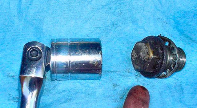
luck.
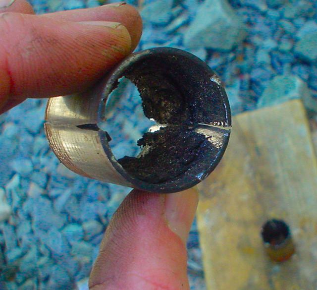
They used and air hammer and smashed the hell out of the ends!!!!!!!!
The photo above is the mushed bushing and spindle pin!!
They also had a spring compressor but torched the springs to cut them..
Barbarians. So no Tokico vs. Stock comparison shot!
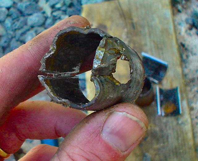
Here is the mushed other side and look what they did to my E brake bracket!!! Grrrrrrrrr
So I went home and took out my frustrations!
Sorry I was angry and did not hake any pics.
I managed to cut the spindle pin where the hub meets the control arm.
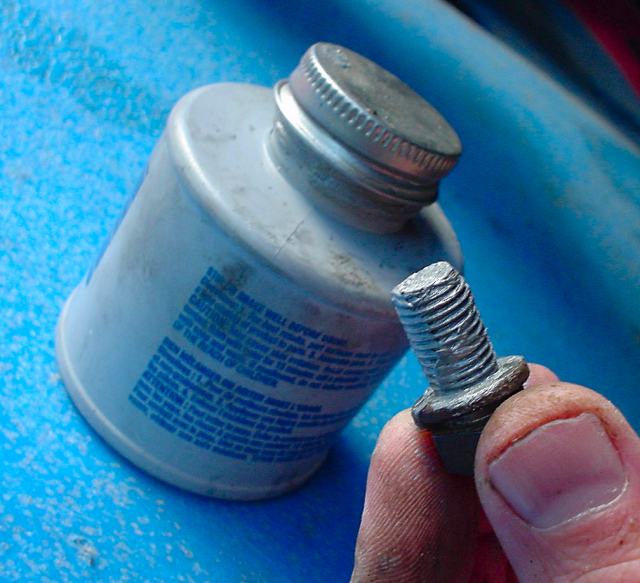
I sprayed lots of penetrating oil in the lock pin hole
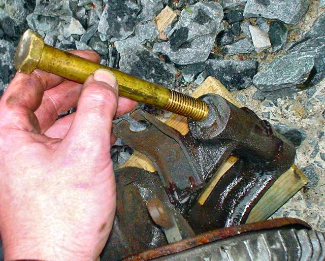
I then used my big bolt as a drift and pounded out the spindle pin
OK, one pic for ya that I found.
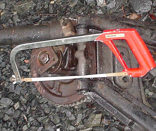

OK, back to work. Here is the other control
arm.
See the space between the control arm and the hub. That is where you cut.
I used a hack saw but I later bought a saws-all for the bushings... bite the
bullet and buy the saws-all now (don't forget to get a metal cutting
blade)

Another pic of the same.
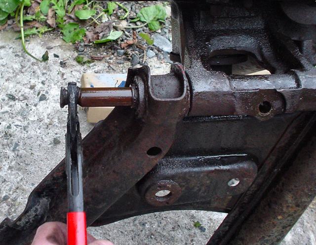
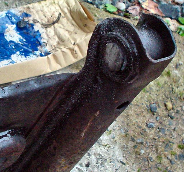
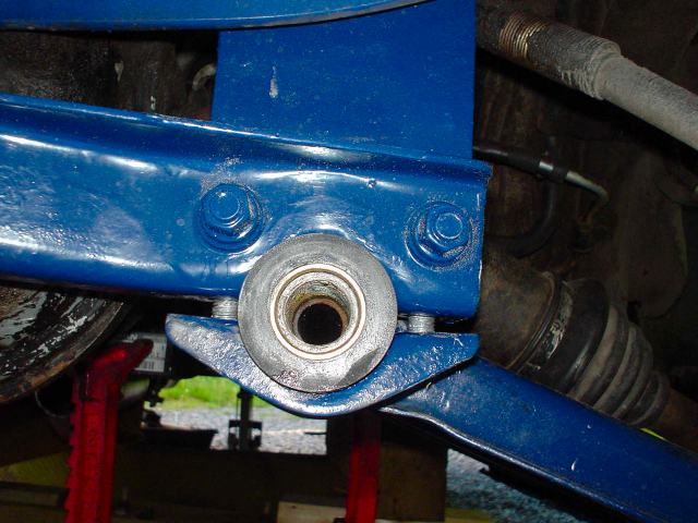
For reference, here is the outer control arm bushing where the spindle pin
passes.
See the bushing sleeve that needs to be cut out.
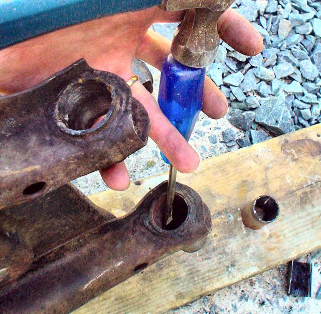
Ok here is a "simulation" of how I got the first spindle pin out:
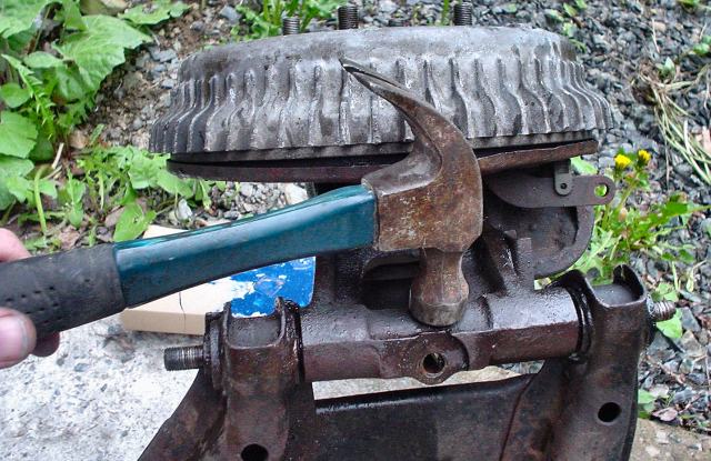
Tap outside to shock rust. Spray lots of penetrating oil.
Let sit over night if you have time
Hammer pin in one direction
Hammer pin back in other.
Flip when movement is 1mm then repeat until pin moves 1 cm in each direction
Yeah Right! I was lucky to do this the first time on the other spindle
pin.
I guess the good ol' boys at the muffler shop broke the rust!
Well time to face reality and dispose of my visions of grandeur!

Cut off the bushings at the joint
Look how easy that spindle pin comes out... it is an optical trick!
That is the cut
off end which is only 3" long.

Cut off the other end.
We have separation!
OK, back to "la la" land for a moment. Lets get
the rest of the spindle pin out!
Spray some magic oil
Hit with a drift
Hmmm lets cut it here and I'll tell you a funny
story.
Me: "Honey, when I am at work tomorrow, can you drop a part off at a
machine shop?"
She: "What do you mean? I can't do that! What do I say to them? What if
they ask me questions?"
Me: "Don't worry, I called them and they know what to do"
She:" Well OK"
Later the next day...
Me back home from work: "Did you get the work done?"
She " You !@#$$$ owe me big time!!!"
Me "What?"
She "That place was full of greasy men who leered at me!
You sent me to the wrong building so the manager made me walk through the shop!
We then went to the office area and the whole place was filled with posters of
naked women on the walls!"
Me "hehehehe"
She "!@@#$$%"
So there you go. Take the strut to the machine
shop and have them press out the spindle pins for $20.
Only cost $10 if your wife takes them LOL!!!!
Be sure to have new spindle pins on hand!
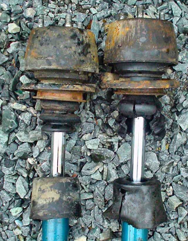
Ok sidebar to forensics. Strut insert on left is driver side, one on right
is passenger.
I was getting a loud clunk from the passenger side when accelerating and going over
bumps Plus! I had the squirreliest car around.
I knew my strut was worn but I did not know how bad it was!
Now I see the extent. A screen door piston actually has more damping than that strut.
Look at how the bump stop is destroyed too!
Finally, look!!! Two different part numbers for left and right!
btw does anyone recognize the manufacturer?
"It's time to burn" a great song for driving!
Well, there is the outer bushing and sleeve. Gotta get them out.

Burn baby! Look at that torch action

Another shot for you pyros.
See how the bushing can be pushed out once it softens.
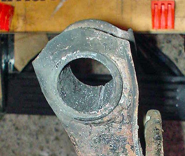
Just get enough rubber out of the way.
You need to see the cutting
depth of the sleeve when you attack it with a hack saw or saws-all.
Drive out the bushings with a flat screw driver or socket.
No, I did not do that! Those muffler shop monkeys did!
Pop!
Another

No more!
Yeah one more... courtesy the muffler shop boys!
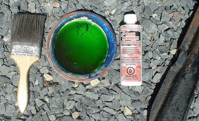
Lets neutralize the rust!
Phosphoric acid.
Rust turns green!
Sorry, no picks of removing these parts but it should be obvious.
Some 14mm sockets and wham bam done!
The dusty coating is pollen.
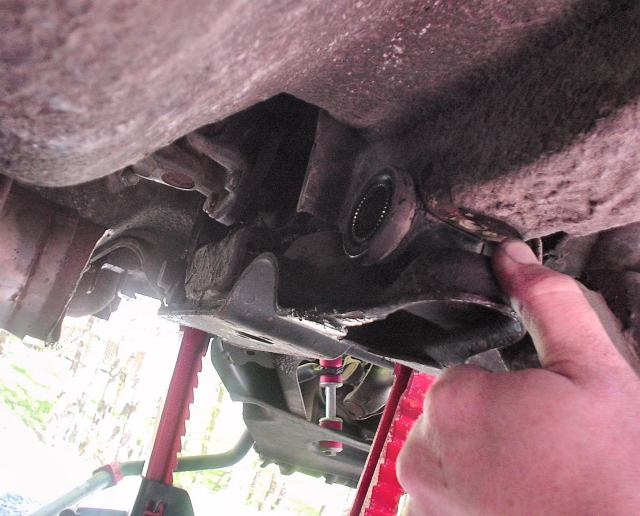
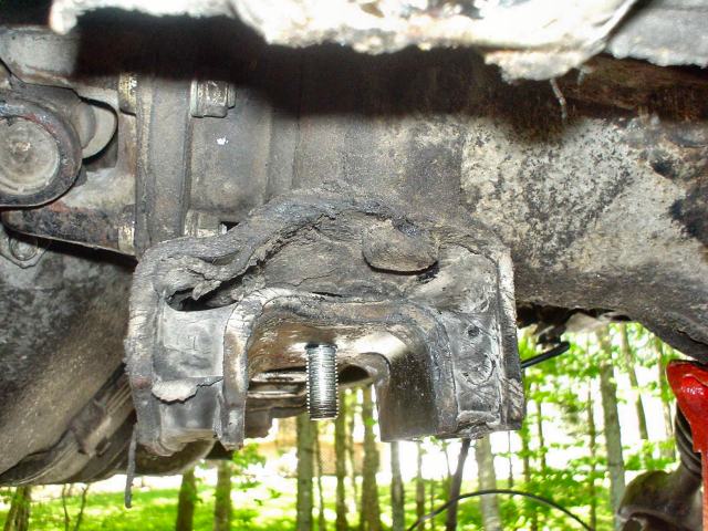
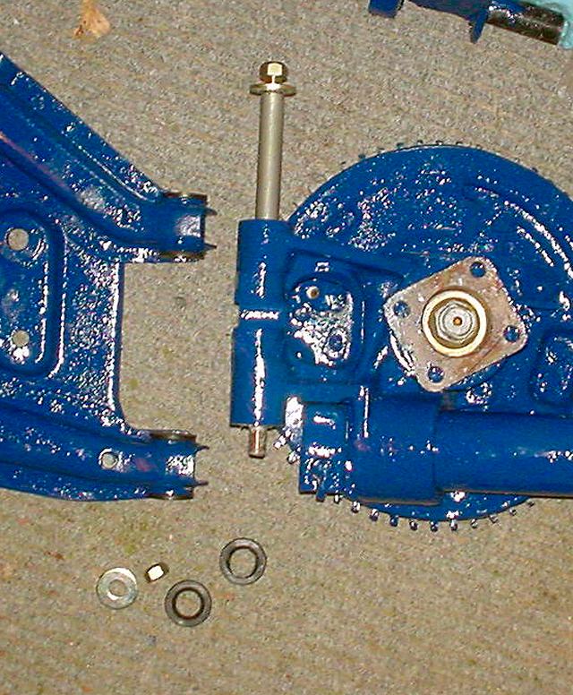
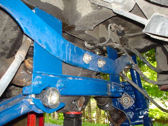
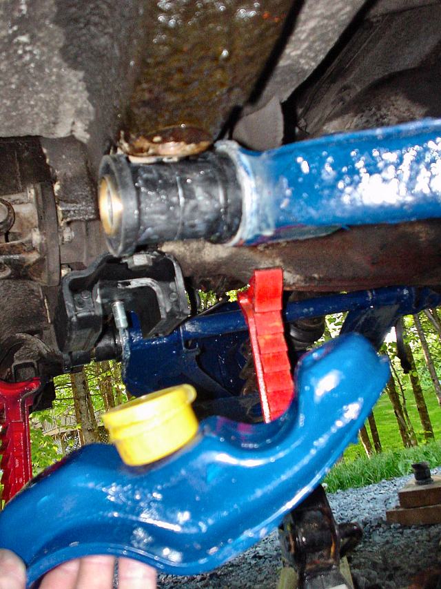
Here is another part that I did not photo document well. Removal of front differential mount.
With the control arms and struts out. Access to the differential mount is
so easy (if you can call it that)
Here is another view of the wide open space
First, remove the front differential cross member.

Well supported differential
Ugh!
Makes me dizzy!
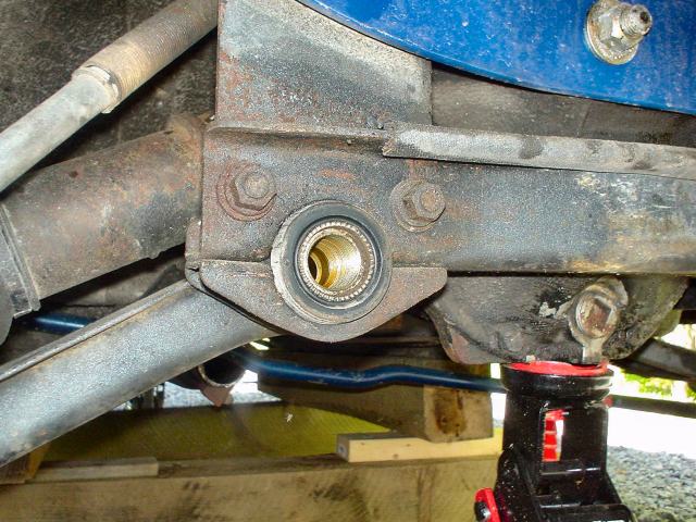
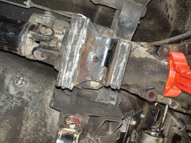
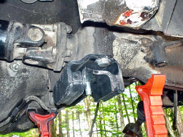
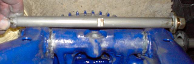
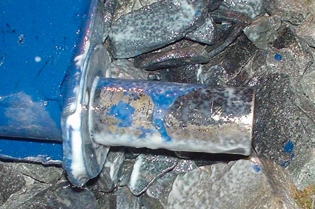
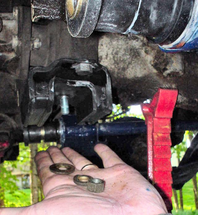
Follow this with some creative wrench and
socket techniques to loosen the nuts at the top of the differential.
17mm socket does the trick.
The differential mount will then drop off.
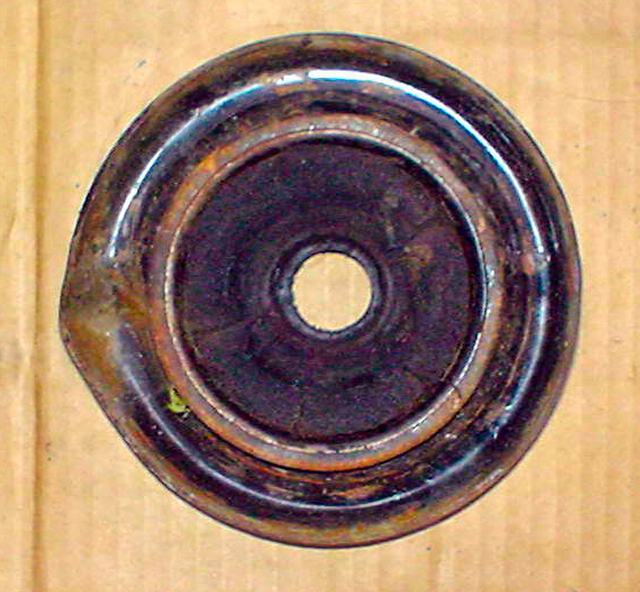
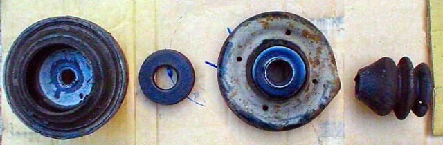
Note, the rubber is still intact and
firm however it is shot. I'll show you how to tell.
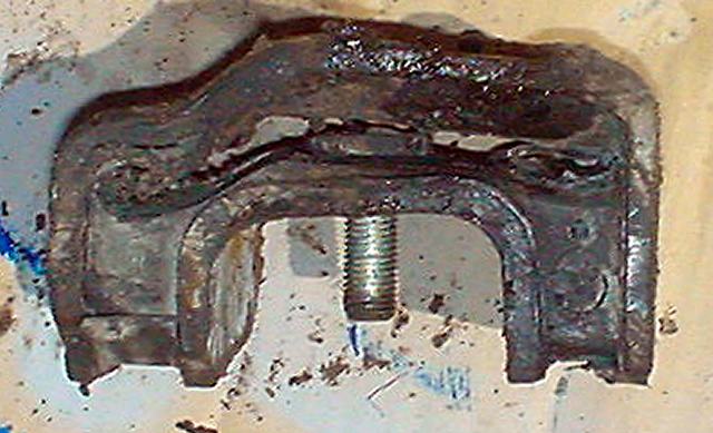
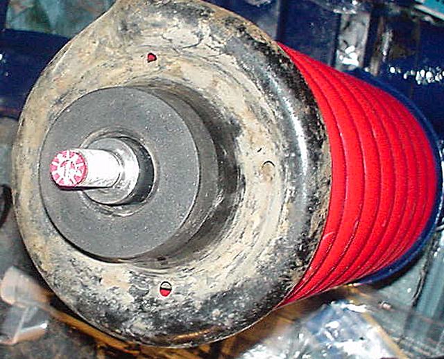
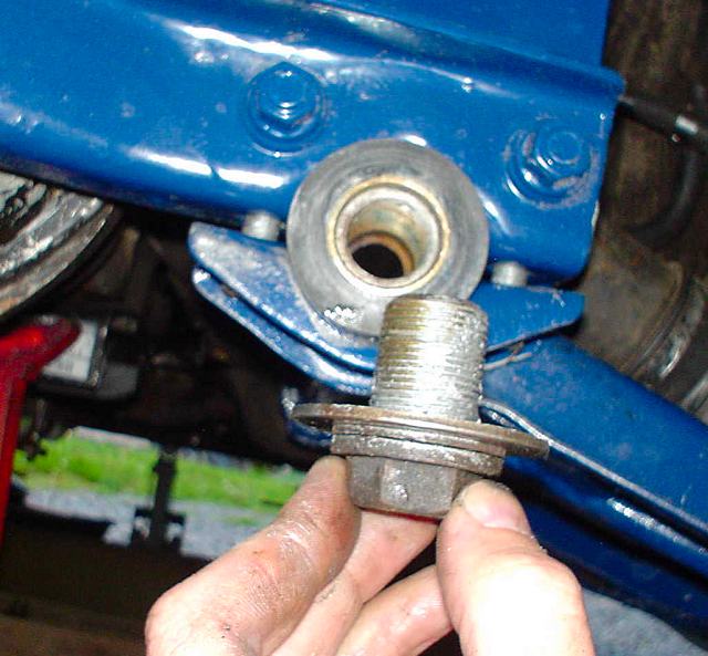
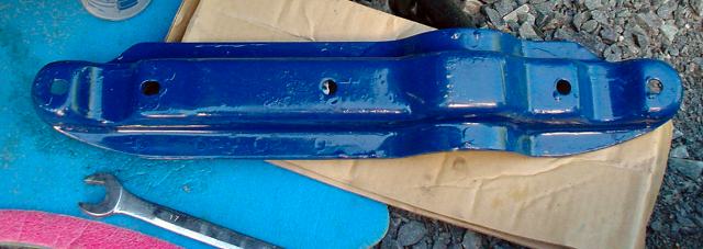
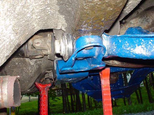
Here is a side view. See the rubber is dirty but intact.
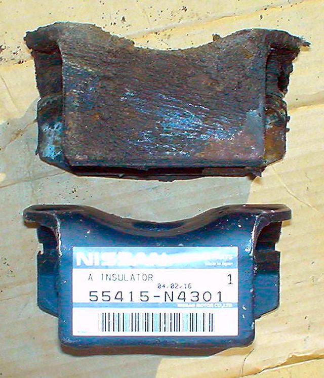
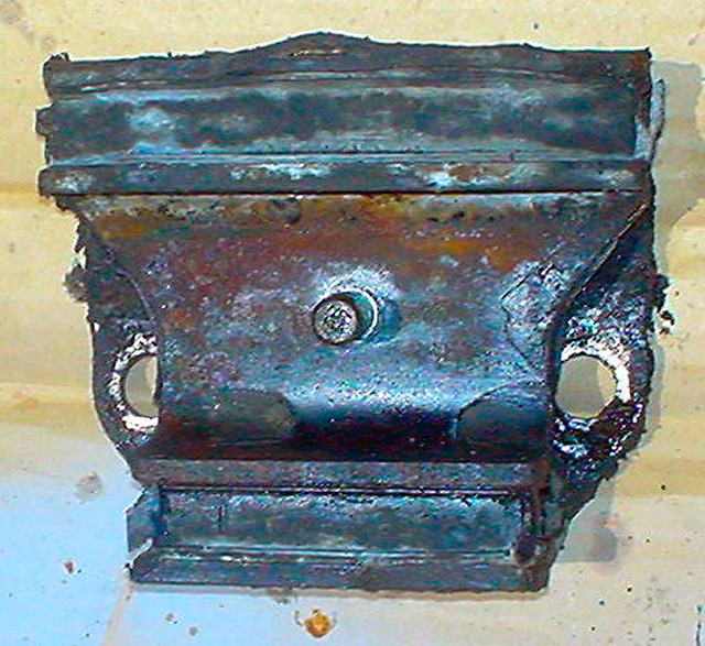
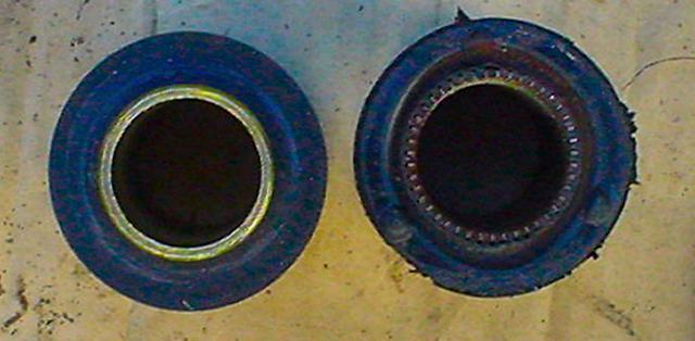
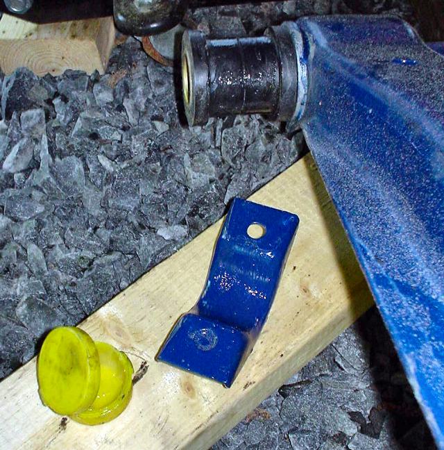
Here is a front view of old vs. new

Here is how you can tell the differential mount is shot. the yellow line
should be ~ 1cm
Look at how the worn one has dropped!
Actually the nose of the differential has "reared-up" since this
piece is constrained at the bottom.
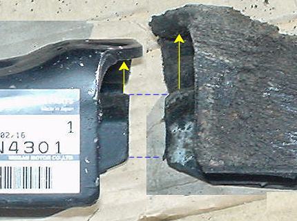
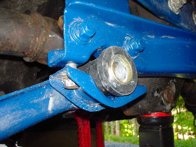
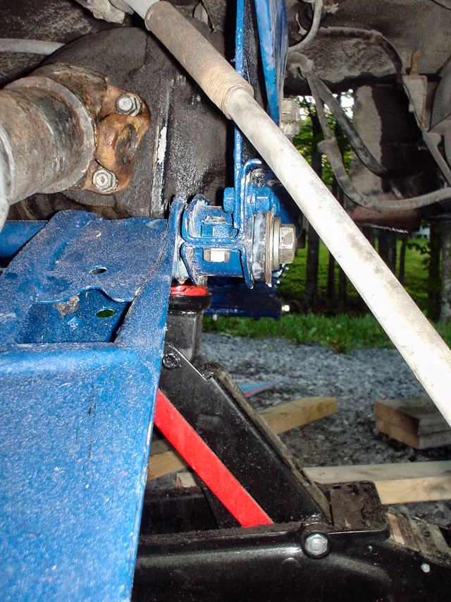
This is better. Look at how the differential mount
has been pulled up from where the bracket mounts on the cross member.
Such a loverly site!
Be sure to completely install the differential mount and torque tow bolts to factory spec.
now.
It will be too difficult to do this later.
Listen!
Can you here that?
What?
No "Clunk" :)
Let's get this show over... final stretch.

Use lots of anti-seize (grey gunk) and trial fit the spindle pin in the
hub.
You may need to "round file" some of the rust and dings from the removal
process.
Prepare thy bushings! New vs. Old.
Remember to apply lots of silicon grease from the bushing kit.
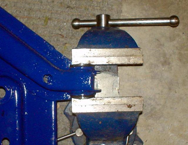
Use a vice to squeeze the bushings in place.
Some clever people freeze bushing to contact them for a better fit.
Line up the control arm (with bushing) and hub/strut assembly.
My bushings were too thick! so I had to sand them. Maybe freezing would have
worked?
I am impatient I guess?
Note that the spindle pin is not symmetrical and it can be inserted two ways:

Correct
Incorrect
The flat spot must line-up with the hole for the locking pin!
Likewise, the spindle pin's flat spot must be aligned with hole.

Aligned

Not Aligned
You can be close with this one as the lock bolt will align the pin as it
pushes through.

Once everything is aligned, drive the lock bolt in.
Use lots of anti-seize.
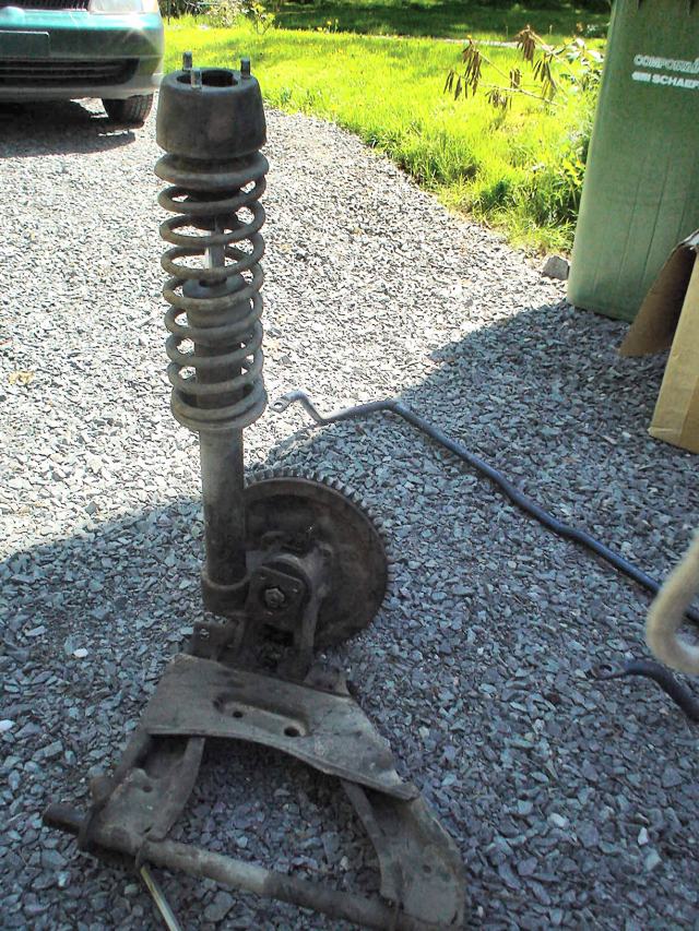
Here are some pics of the top of the strut assembly
Top spring perch
Assembly from left to right corresponds from top to bottom.
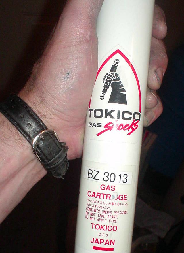
Strut inserts for 280z '77 rear
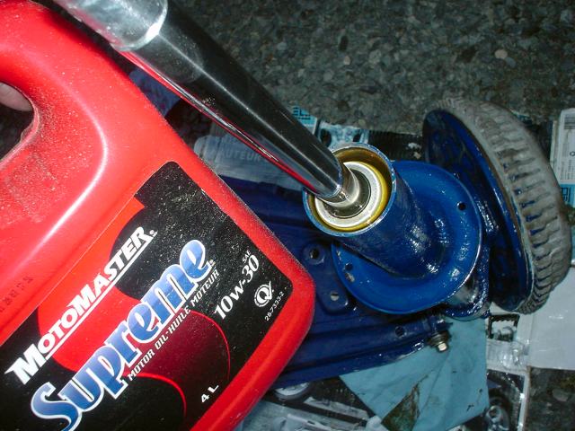
Clean the inside of the strut tube.
Pop in the strut and fill with oil.
The oil is for transferring heat.
The front struts did not require the spacer however the rear did.
It fit's into the gland nut supplied with the strut inserts.
Tighten the gland nut with a pipe wrench.
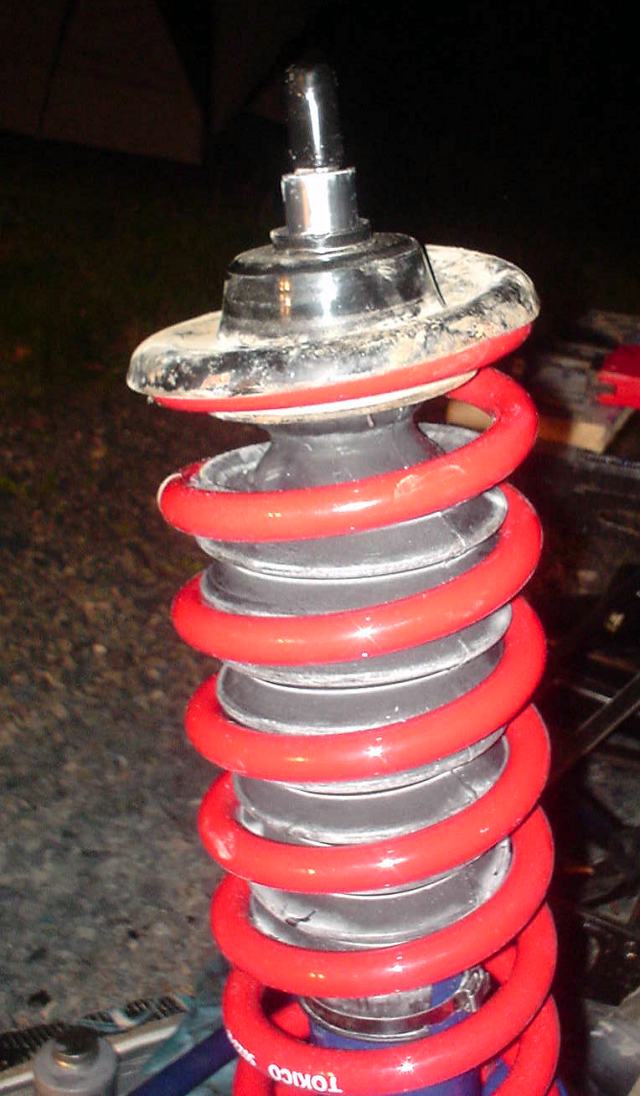
Pop on the spring and perch! I know it is upside down! It was 1am!
btw the Tokico's do not need to be compressed!
Also note the metal CV joint boot strap! The rubber boot is from KYB and it has a
built in bump stop.
The wire wrap tie included in the KYB kit is a frail joke. Buy a
metal CV joint strap tool!

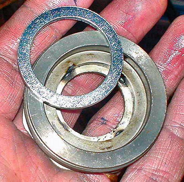
A rubber spacer goes on the top. (A bearing is on the front strut in the
same location)
Ahhh the adjustable Tokico!
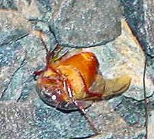
June bugs are driving me crazy!
I'm calling it quits for the night!
No I did not kill him. He is just stupid and landed on his back!
Ahh a nice sunny day!
Bolt the upright assembly to the floor
Grease up the bushing mounts. I use the silicon stuff from the bushing kit
and lithium grease for over kill.
Fit the strut assembly and snug the top bolts.
Grease up the clamp and bushing (note this
photo is passenger side)
Support the control arm by clamping it at the rear inner bushing.
Yet another.
Reminder! Use lots of anti-seize!
And another.
Repeat installation of passenger side strut/control arm assembly
Snug the big nut
Side view
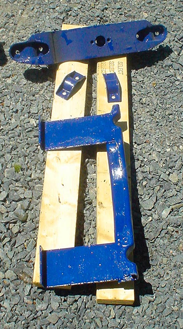
Photos of Front Differential Cross Member
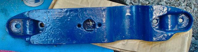
Another
Grease up front inner control arm bushings and corresponding part on cross
member
Attach cross member to new differential mount using washer, lock washer
and nut.
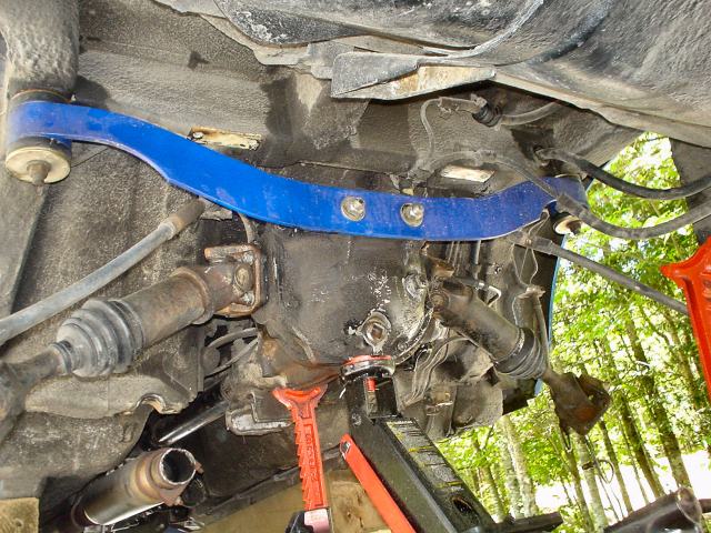
Bolt cross member to unibody and attach big bolts.
Note this job required some slight shifting of the differential and prying to
fit the cross member in place.
I also had to loosen the rear differential mount nuts (at moustache bar)
My wife is a great sport and she drove the bolts home as I pushed the
differential!
She was on her back with head and shoulders under the car! I wish I took a photo!

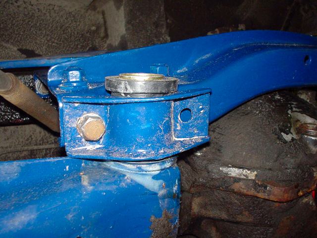
Fit the rear sway bar to frame (here is one of the mounts and poly
bushing).
Attach sway bar to control arms with end links

Extra Photo


E Brake mount and spindle pin.
Note the new rubber washers squirmed out when I tightened the spindle pin nuts
on all four!
Attach Drive Shafts!
Finally:
Torque components to body according to factory
specs (front differential cross member and control are uprights.
Torque rear inner control arm bushing clamps to factory specs
Torque big control arm bolts
Torque spindle pin lock
Torque spindle pin ends
Torque rear moustache bar to differential nuts
Torque front differential mount to cross member nut
Torque the center strut nut.
Re torque moustache bar bushing nuts
Attach E Brakes
Bleed Brakes
Attach wheels
Do a once over to make sure every thing looks correct
Drop car
Back car on ramps (rear wheels on ramps)
Loosen and re-torque large control arm nuts
Loosen and re-torque spindle pin nuts.
Enjoy!
Check and re-torque after a few hundred miles to be safe
Don't forget to fix that muffler!
My right wheel bearing is now crapping out. It
is either due to the new geometry and the beating it took from the bum strut
or it is another gift from the muffler shop monkeys!
Stay tuned for rear wheel bearing change from yours truly.