Thanks to Wayne Monteath for disassembly and tutoring!
Exploded Views (click to expand)
Nissan Replaceable Part Numbers:
Breaker plate: 22136-H9501
Pickup coil: 22229-Q1700
Magnet: 22158-S6700
Stator: 22163-Q1700
To Disassemble:
Follow from bottom to top with the following notes:
- remove stator first
- use two flat screw drivers at 180° apart to pry reluctor up with a gentle and even force. Liquid wrench on the shaft helps.
- parts are brittle so be careful
To Assemble:
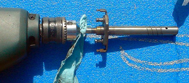
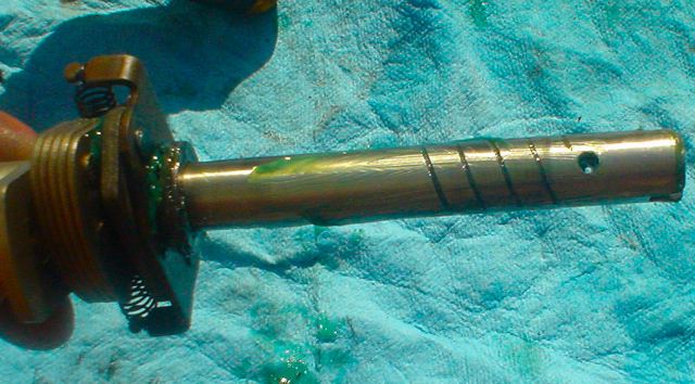
Place shaft in drill and spin. Use 3M "scotch brite" pad to clean
machined shaft

Voila.
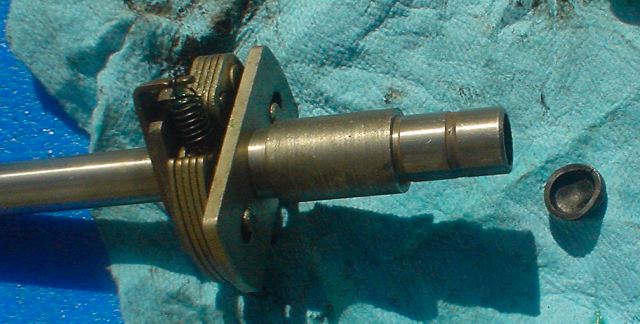
The grooves pull oil into the shaft bushing area for lubrication.
The other end is where the outer shaft fits over and ultimately connects to
the weights.
The weights and springs connect to the middle section.
Note: Each piece was cleaned of debris and gunk using a "scotch brite" pad and a shot of carb cleaner.
Here is a top view of the shaft where the weights and springs attach
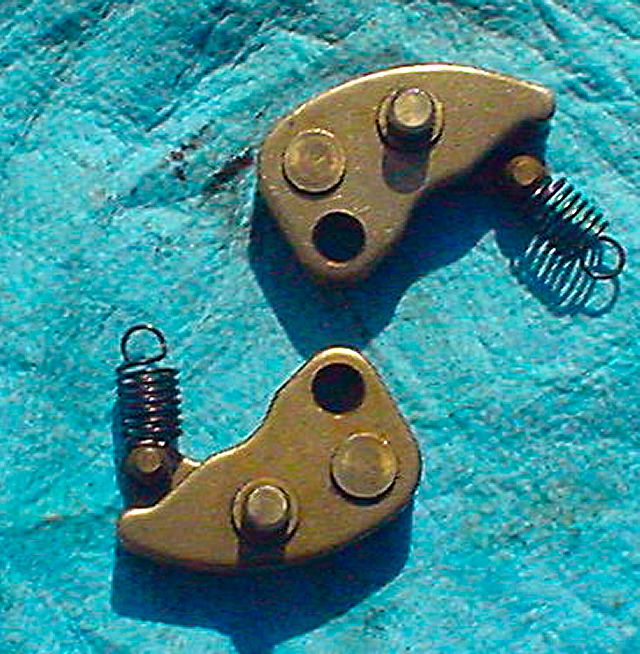
Here are the two weights and springs.
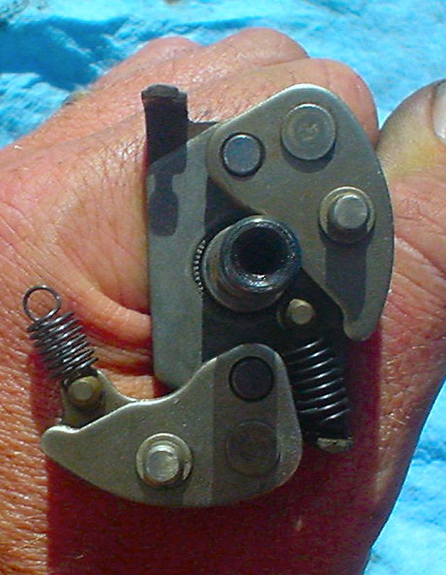
Dry fitting the weights and springs. Heart of the mechanical advance
mechanism.
As the distributor accelerates, the weights travel outward and the pins rotate
the breaker plate.

Preparing the main shaft for mounting weights and springs.

Weights Installed
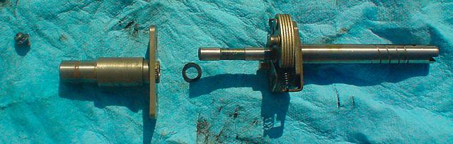
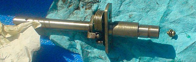
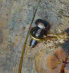
Here are the next parts to assemble:
- screw with lock washer and washer
- counter weight guide for mechanical advance
- washer
- main shaft with counter weights installed
Another view
Grease the washer and install then grease the counter weight guide and install
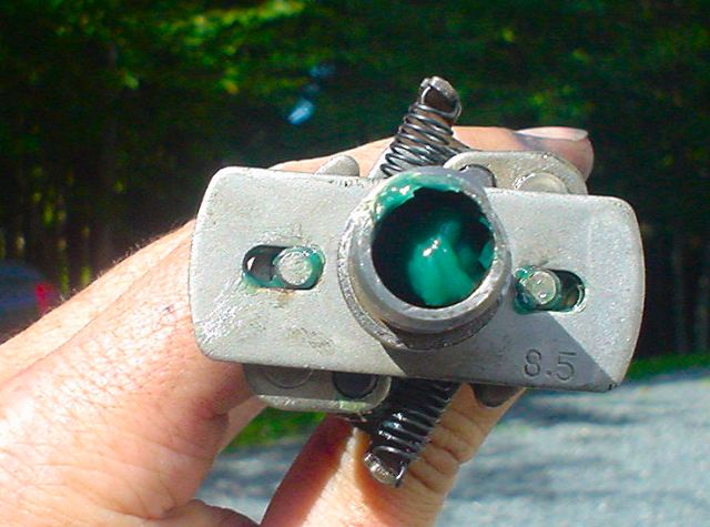
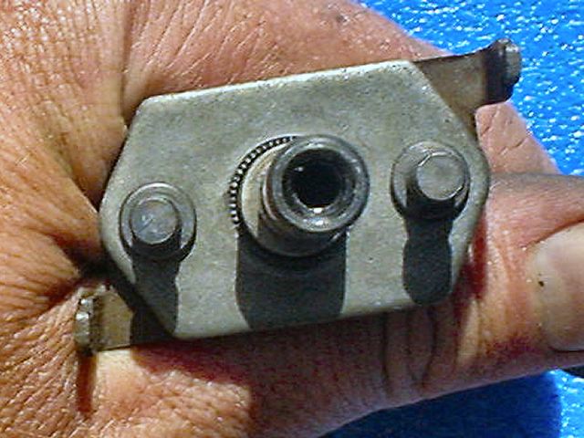
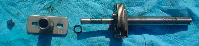
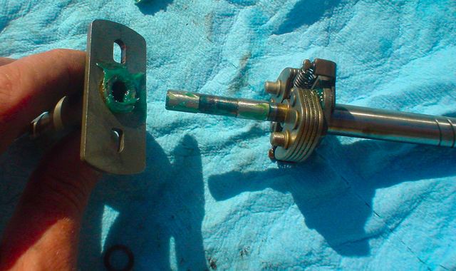
Here is the counterweight guide installed. "8.5" is the advance in
degrees.
IMPORTANT! It is
possible to do this 180° incorrectly... I did.
The way to properly align is to ensure the flat section on the counterweight
guide is on the same side as the short side of the slot at the other end.
Look at these two pictures to see:

Note flat spot for alignment
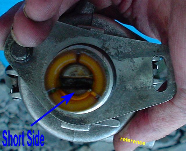
Note short side for alignment
Install end screw
Install rubber cap.

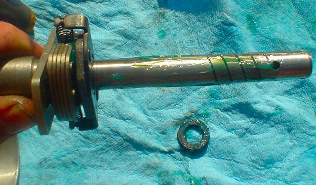
Bushing washers that separate main shaft from body.
Keep in order
All appear to be metal with the lighter colour in the middle.
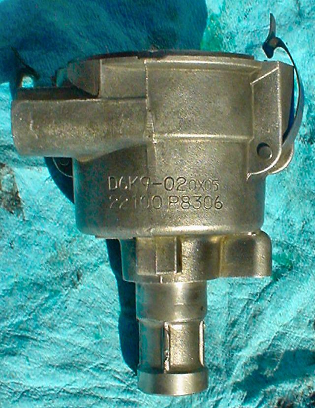
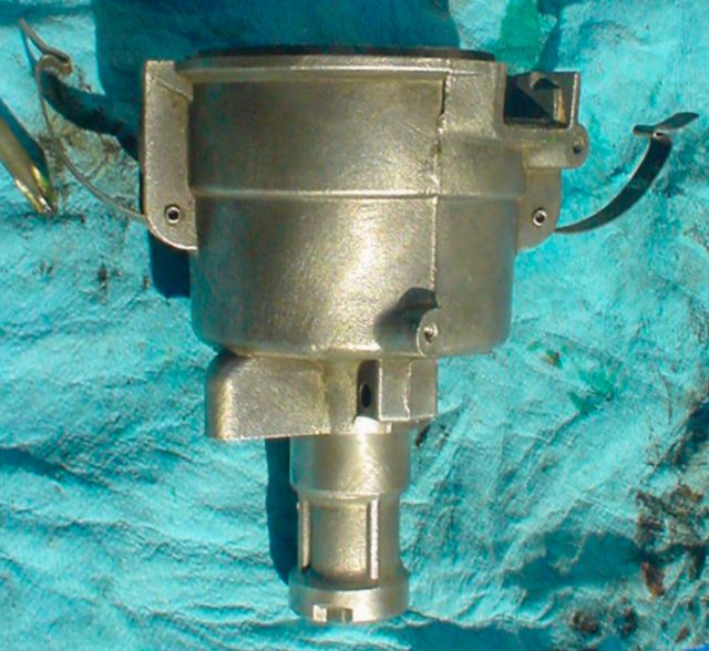
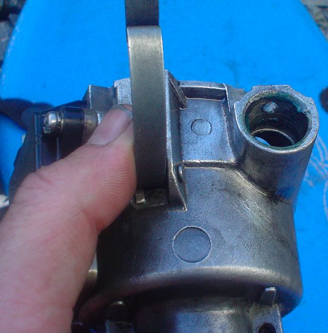
Here are a few reference shots of the distributor body. I just brushed it with a wire brush fitting on a drill.
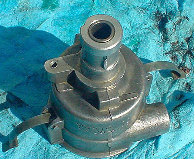


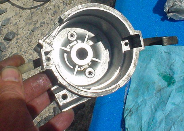

Apply grease to interior of body where main shaft will fit.
Grease bushings
Grease the main shaft
Mount the 3 bushings
Insert the main shaft into the body a few times to work the grease in.
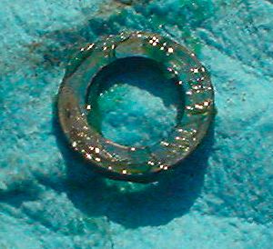
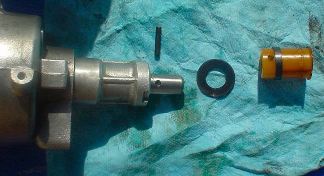
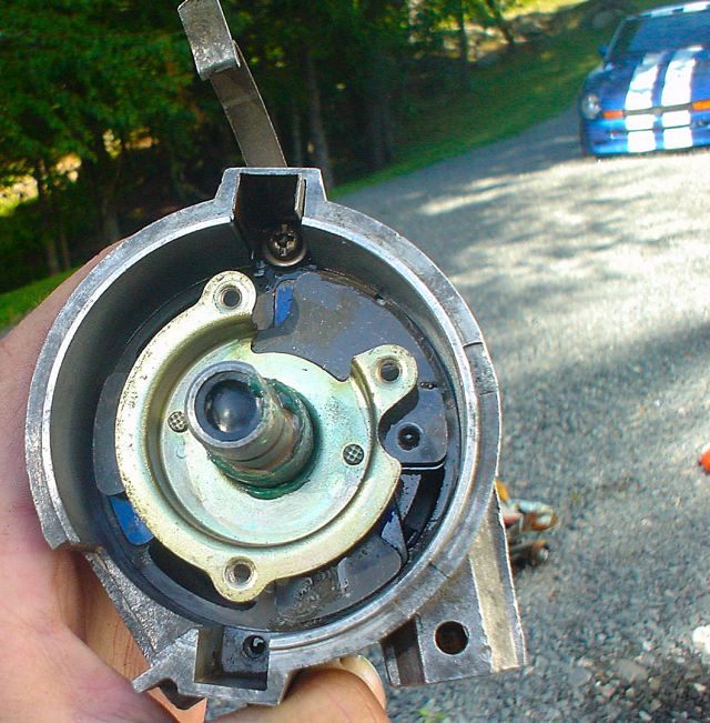
Here is a photo showing the end pieces:
- pin
- bushing washer
- plastic fitting with metal ring
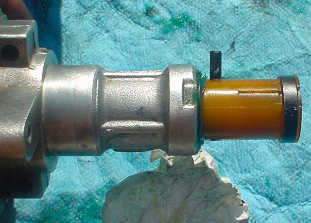
Assemble and fit the pin
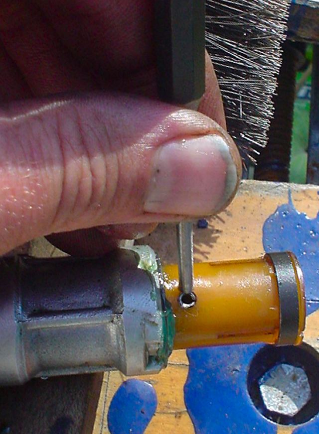
Use a punch to install the pin
Here is the other end of the shaft being held to assist in installing the pin.
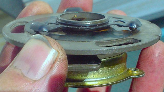
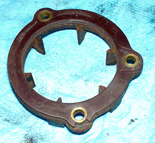
Now some pictures of the breaker plate
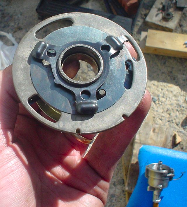
Rotated in one direction.
The 3 "lumps" have ball bearings underneath

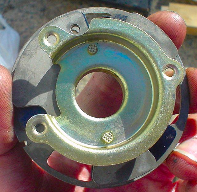
Rotated in the other. Note the rust under the ball bearings. I had to clean it
off.

Rotated to one extreme
Rotated to other extreme
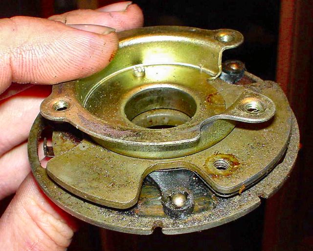
There are also three on the other side of the plate. They are held in place
with a plastic triangle shaped piece that is sandwiched between the metal
pieces.
Note this breaker plate is a damaged one I had laying around and the bearings
are exposed. Normally they are under the outside plates.
Here is a busted plastic bearing holder.
When this happens, the ball bearings are usually rolling around at the bottom
of the distributor housing.
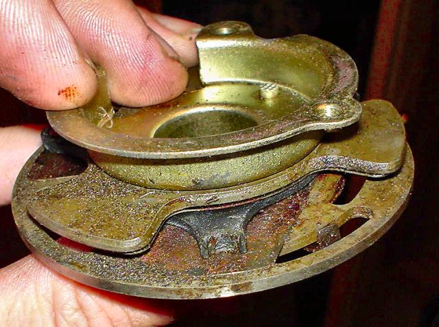
Better view of bearings.
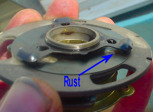
The rust is under the bearings
There are a few ways of dealing with the rust and
lubricating the bearings. White lithium is a favourite.
I used a rust inhibiting oil to stop further rust and lube the bearings.

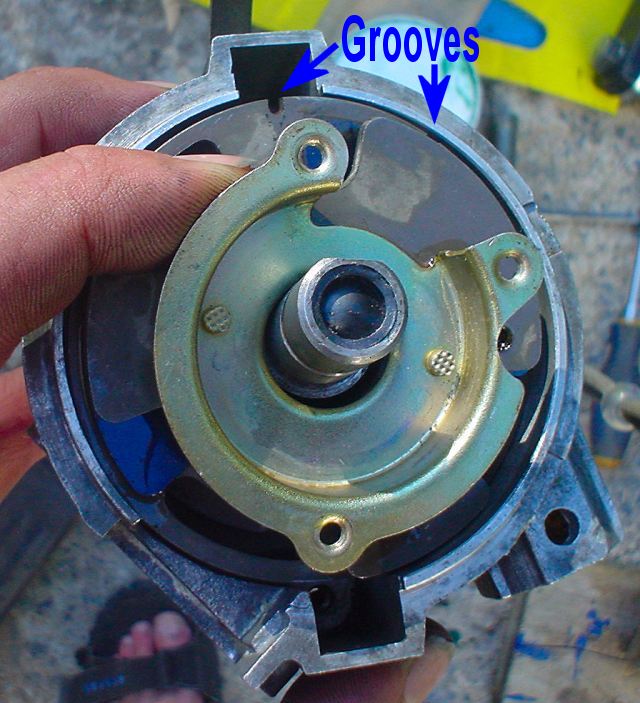
Install the breaker plate. Note the two grooves on the edge.

This is a key to prevent installing the distributor cap incorrectly AND it
also locks the breaker plate
Here is the key installed and the breaker plate groove locked into place. Note
the unused groove to the right.
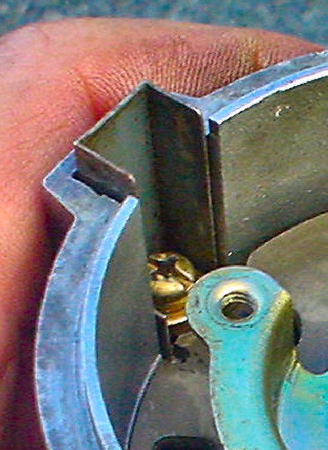
Close up of the groove and key

Install the other screw to hold breaker plate and install rubber fitting where
ignition module wires pass.

Prep the ignition module:
- clean all debris and corrosion from metal side where it connects to the distributor body
- use a contact cleaner like Deoxit to further enhance conductivity of ignition module to distributor body
- also clean electrical contacts
- note, some recommend using a heat sink
compound between the body and ignition module to transfer heat from the
transistors as heat is what kills them.
Wayne and I feel that the compound may couple engine heat into the ignition module and also decrease conductivity of the the modules ground through the two points.
A neat solution would be to mount a heat sink on the ignition module and mount it remotely then run a separate ground to the car's body.

Fit the ignition module and spray screw contacts with Deoxit.
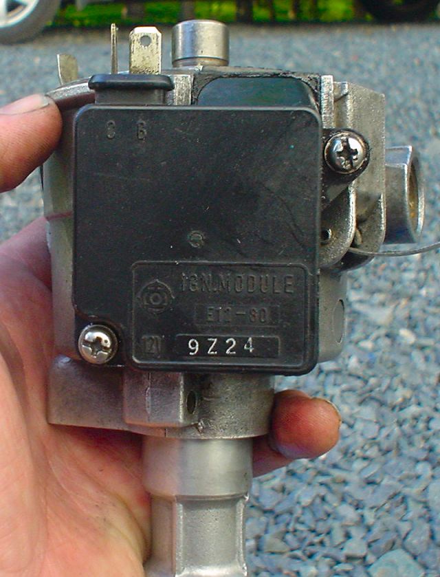
Install screws
Top view
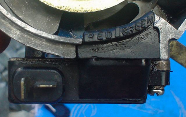
Note the colour key stamped in the rubber for connecting the two wires
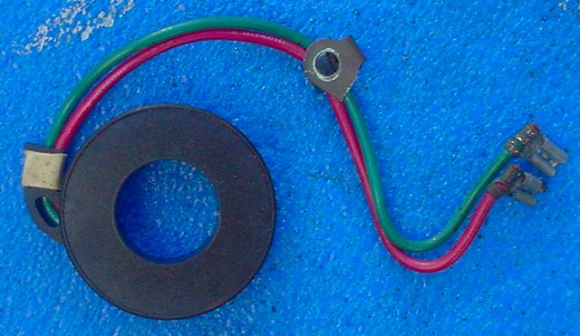
This is the coil that fits on the breaker plate. Nominal resistance as
measured by a digital multimeter is 400 ohms or what is spec'd in your Factory
Service Manual .
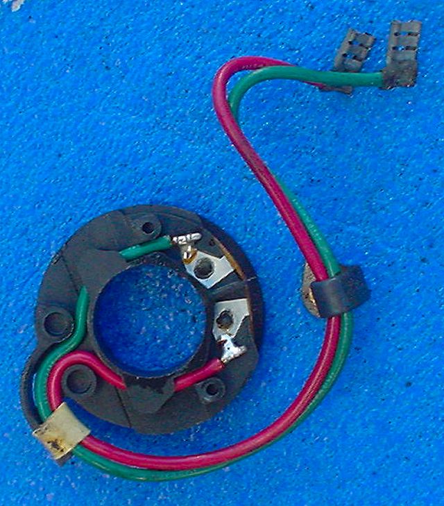
Another view

And another
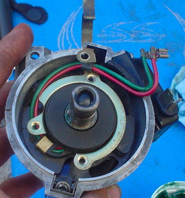
Fit the coil and wires into the breaker plate. Spray contact cleaner on the
connectors.
Connect wires to ignition module.
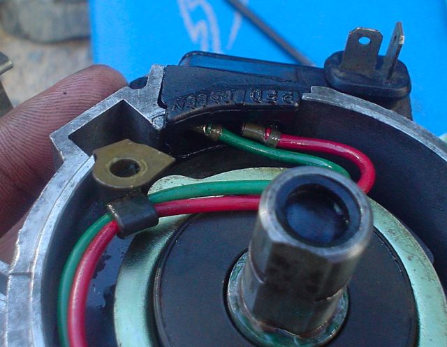
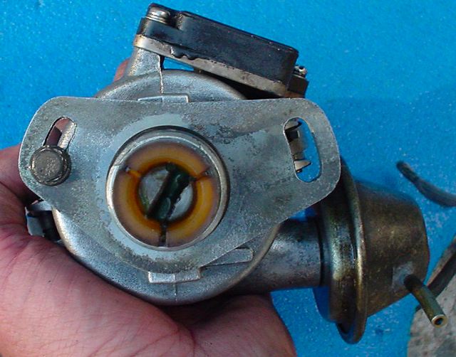
Here is where the vacuum control (vacuum advance mechanism) installs. Lube it
with anti-seize or grease.
The hole just above the red and green wire is where the screw that holds the
vacuum control arm goes
Here is the pin/screw that secures the vacuum control arm to the breaker
plate. A ported vacuum causes the arm to retract and pull the breaker plate
clockwise. This advances the timing.

Install the larger screw and washer to secure the vacuum control.
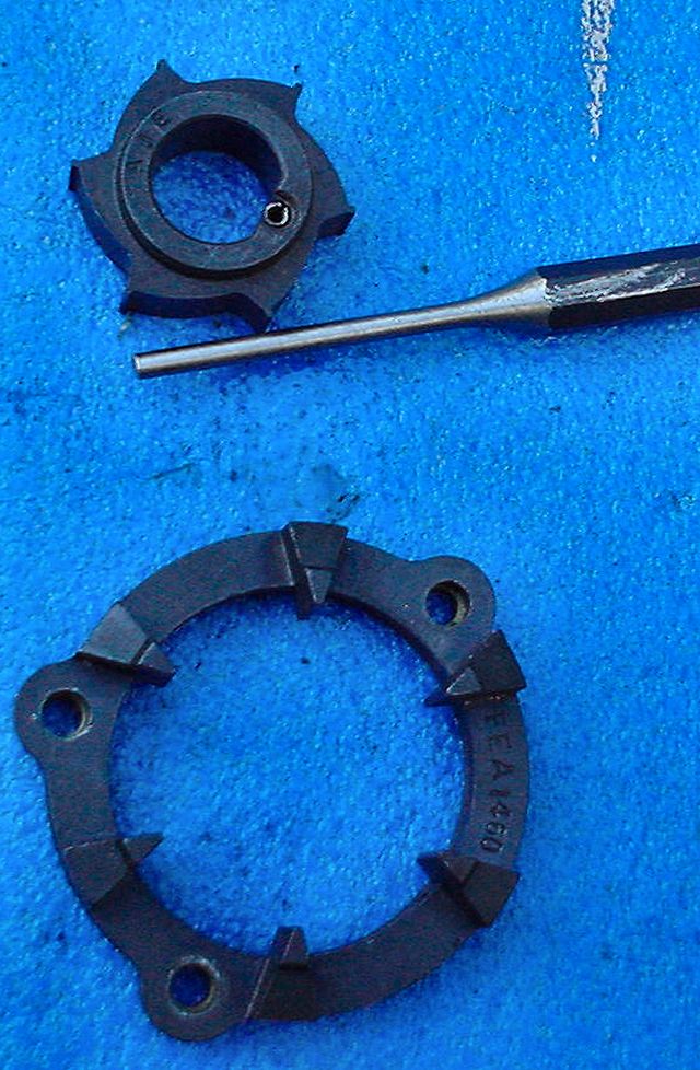
Reluctor (smaller ring) and Stator
The back side of the stator is made from a brittle magnetic substance that can
break easily. Just snug the screws.
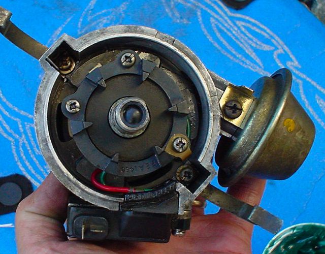
Install stator.
3 screws are left loose at this point
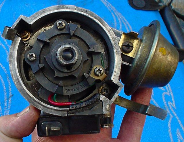
Install reluctor
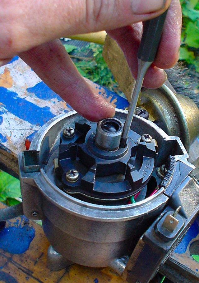
Install reluctor pin.
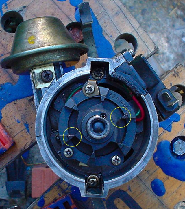
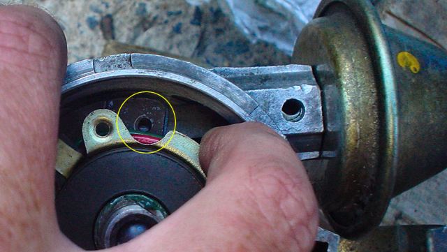
Installed stator and reluctor but not aligned.
Look at space on left yellow circle (none) versus the right (too much).
The stator must be repostioned so that the reluctor's tips are all the same
distance from the stator tips when rotated.
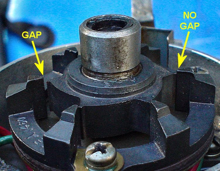
Here is another view of the problem
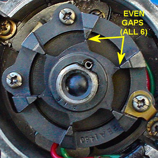
Align the stator and then lock it into place with the 3 screws
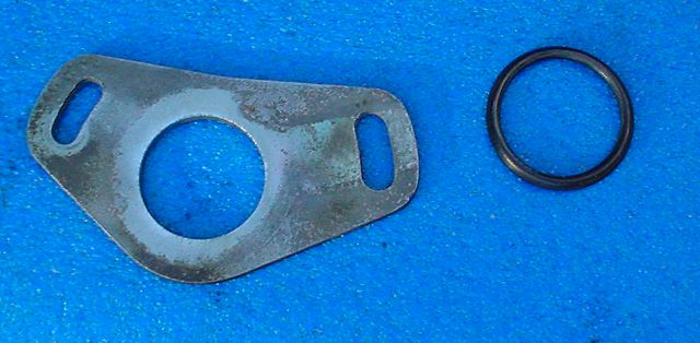
Bottom plate and O-ring
Installed!
Further info:
http://www.geocities.com/zgarage2001/engine.html
http://www.jrdemers.com/280ZX/distributor/distributor.html
http://home.att.net/~jason510/Dizzy_FAQ.htm
http://home.att.net/~jason510/dizzy_specs.htm
http://www.atlanticz.ca/zclub/techtips/distributor/index.html
Wayne's famous post From Zcar.com:
Author: 79-280-ZX
Date: Nov 17, 2001 12:49pm
This is applicable to the Hitachi Distributor model D6K8, D6K9, D6K80 and
D6K81 part number 22100-P9101 found on a 1979 N/A L28E.
Inside the distributor there is a part called a Breaker Plate Assembly, part
number 22136-Q1700. It is two metal plates that has a triangular plastic plate
with three ball bearing, one at each point of the triangle, sandwiched between
the two metal plates. The ball bearings keep the two plates apart.
The plastic triangle acts as a race to keep the ball bearings in place. The
bottom plate is fastened to the distributor housing. The top plate is
connected to the rod from the vacuum advance, part number 22301-N4700 (this
number is for reference ONLY, there are 12 different vacuum advance modules).
The Pickup Kit, part number 22229-Q1700, is fastened to the top plate of the
Breaker Plate Assembly. The Stator, part number 22163-Q1700, is placed on top
of the Magnet, part number 22158-S6700, and both units are fastened to the
Pickup Kit.
Finally, the Reluctor, part number 22115-Q1700, sits on the distributor shaft
and is held solidly in place with a pin. It is located mid-way between the
Rotor and the Mechanical Advance Mechanism.
There are six teeth on the Reluctor and six teeth on the Stator. Each time all
the teeth line up, the magnetic field, that is always being produced by the
magnet, is altered.
Each time the magnetic field collapses and expands it acts as an on / off
switch for the current flowing through the Pickup Kit.
The distance between the teeth on the Reluctor and the Stator is called the
Air Gap and should be between .006 and .016 inch. This should be measured with
a brass feeler gauge because of the magnet.
The Pickup Kit is the part that sends pulses to the Transistor Ignition Unit
on the outside of the distributor.
The operation of the Transistor Ignition Unit is outside the scope of what I
am trying to explain at the moment but it is basically an electronic filter
and a high current switch. The filter part takes the input from the Pickup Kit
and makes it into nice, clean, square waves. These square waves are sent to
the high current switch part which is connected to the (-) side of the
ignition coil.
The Ignition Module for 1979 to 1981 is Nissan part # 22020-S6702 (aka
E12-80).
The Ignition Module for 1982 and 1983 280ZX N/A (E12-92 Nissan # 22020-W3100
or E12-93 Nissan # 22020-P9700)
Each time the high current switch closes there is current flow between the
battery and ground through the '+' and '-' terminals on the ignition coil.
Current flow in the Primary Side of the ignition coil induces a higher voltage
in the Secondary Side of the ignition coil.
The Secondary Side of the ignition coil now contains around 50,000 volts. When
the high current switch opens there is no current flow in the Primary Side of
the ignition coil and the Primary field collapses. The voltage stored in the
Secondary Side of the ignition coil now has to go somewhere.
When the rotor lines up with a tower in the Distributor Cap the voltage goes
out the high tension lead of the coil to the distributor, down the rotor,
JUMPS to the NEAREST spark plug wire post inside the distributor cap, down
that wire to the spark plug and then BOOM, an explosion in a cylinder.
Z'ed should go vrooom.
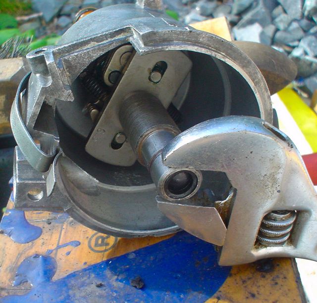
Way back, up in the beginning. I mentioned the Mechanical Advance Mechanism.
There are two key components of Mechanical Advance.
First is the AMOUNT of Mechanical Advance.
For the Hitachi distributors, this is completely controlled by the length of
the advance slot in the Cam Set (part number 22132-P7100). If you don't know
where these are, open up your distributor, take off the rotor, and look under
the Breaker Plate Assembly. Now force the weights out and look for where you
see the pin moving in the slot. Once you have seen this, it is pretty easy to
understand how to change the amount of advance. To get less, braze the slot so
it is shorter. If you want more advance, then lengthen the slot.
On the bar with the slot in it will be a number stamped into the metal. It
will be 8.5 or 9. These numbers correspond to the number of degrees that the
rotor will advance relative to the base of the shaft. Since the crankshaft
rotates twice each time the distributor rotates once simply multiply the
number by two to get the total mechanical advance.
The second component of Mechanical Advance is the Advance Curve.
The Advance Curve is controlled by the shape and weight of the weights, shape
of the cam (in between the weights) and the tension of the springs. If you
install lighter springs, the weights will be able to extend out at a lower
RPM. If you install heavier springs, it will take a higher RPM for the weights
to overcome the force of the springs.
Since the Stator is fixed to the Breaker Plate Assembly, which in turn is
fixed to the distributor body, and the Reluctor is fixed to the Cam Set, as
the RPM changes, the weights move, and changes the relationship of the
Reluctor to the Stator.
To check the mechanical advance:
Disconnect the vacuum advance hose and plug it with something.
Set the engine speed as close to 600 RPM as you can and note the timing. Now
increase the RPM to 2,500 and your timing should advance 17 degrees (if the
Cam Set has 8.5 stamped on it). I.E. If base timing is 10 degrees BTDC at 600
RPM it should be 27 degrees BTDC at 2,500 RPM. (See Note at end)
Vacuum Advance is used to advance the spark as manifold vacuum is increased.
It should be noted that Vacuum Advance is primarily for Fuel Economy, and has
no affect on your performance at Wide Open Throttle (WOT), since you have
almost no vacuum present.
As engine vacuum changes the rod attached to the Breaker Plate Assembly moves
the top plate and changes the timing by moving the Stator.
To test if the mechanical part of the vacuum advance is working do the
following:
Remove the Distributor Cap.
Disconnect the Vacuum line at the Vacuum Advance unit.
Connect a vacuum pump to the Vacuum Advance Unit. As you apply vacuum the rod
should retract and the Stator should move. At around 10 - 15 inches of vacuum
the rod should be fully retracted and the vacuum should not change.
If the vacuum goes down there is a leak in the diaphragm and the Vacuum
Advance Unit will have to be changed. You have also just discovered the vacuum
leak that makes the engine run lean.
If the vacuum does not change, and the rod does not move, the Breaker Plate
Assembly needs service.
If you can see ball bearings in the bottom of the distributor you need a
Breaker Plate Assembly anyway.
When the loose bearings end up wedged in the counter - weights for the
mechanical advance that will stop working also.
To check the vacuum advance with the engine running:
Hook a vacuum pump to the vacuum advance unit. Slowly increase the vacuum to 6
inches and at this point engine RPM should start to increase and the timing
should start to advance. At 10 inches of vacuum you should have more than 10
degrees of vacuum advance. (See Note at end)
Just remember that as RPM increases when testing the vacuum advance the
mechanical advance will be kicking in also.
Now hook the vacuum line back up to the vacuum advance unit and increase the
RPM to above 2,500 RPM.
If you started off at 10 degrees you should now have 27 PLUS whatever you got
when you tested the vacuum advance. I.E. 10 + 17 + 10 = 37 degrees @ 2,500
RPM.
Notes:
The manner in which Nissan chose to list the Service Data Specifications for
the Mechanical / Vacuum Advance need explaining.
Centrifugal Advance:
[Distributor Degree / Distributor RPM]
0/600
8.5/1,250
If you have access to a Distributor Analyzer this means that at 600
distributor shaft RPM you should have 0 degrees of mechanical advance, and at
1,250 distributor shaft RPM you should have 8.5 degrees of mechanical advance.
All of this is measured comparing the relative position of the rotor to the
distributor cap tower. Since it is not likely that we would have a $40,000.00
Distributor Analyzer in the closet we need a more practical method to test
this and that would be a timing light. For each complete rotation of the
distributor shaft the Crankshaft has to turn twice.
So the S.D.S. has to be translated into Crankshaft relative information so
that it becomes:
[Crankshaft Degree / Crankshaft RPM]
0/1,200
17/2,500
You simply take the original numbers and multiply each one by 2 and now you
use the timing mark on the Damper Pulley.
This means that at 1,200 Crankshaft RPM you should have 0 degrees of
mechanical advance, and at 2,500 Crankshaft RPM you should have 17 degrees of
mechanical advance.
Vacuum Advance:
[Distributor Degrees / Distributor mm Hg (in Hg)]
0/200(7.9)
7.5/350 (13.8)
This one has to be converted into:
[Crankshaft Degrees / Distributor mm Hg (in Hg)]
0/200 (7.9)
15/350 (13.8)
Vacuum is measured in mm of Mercury or (inches of Mercury) with a vacuum
gauge. Vacuum is applied to the Vacuum Advance with a hand held vacuum pump.
In the above example when 200mm (7.9 inches) of vacuum is applied you should
have 0 degrees of advance and when 350mm (13.8 inches) of vacuum is applied
you should have 15 degrees of advance.
The vacuum advance mechanism can be checked with the distributor out of the
engine also. Simply cut a hole in a cheap protractor and slide the hole over
the distributor shaft and fasten the protractor to the distributor body with
tape. Re-install the rotor and apply vacuum and watch how many degrees the
rotor moves. In this case you would use the "[Distributor Degrees /
Distributor mm Hg (in Hg)]" specification.
Wayne Monteath
Masham, Quebec.
1979 280ZX 2+2
1981 280ZX 2+2
Post Edited (May 15, 2:18pm)