![afm[1].gif (132536 bytes)](afm[1].gif)
WHAT AN AFM DOES:
The AFM measures air velocity into the throttle body and sends a corresponding voltage to the Engine Computer/Controller Unit (ECU). The ECU then calculates how much fuel to mix with the volume of air. If the AFM is falsely reporting too much or too little air, then the ECU mixes the incorrect amount of fuel and the car runs too lean or too rich.
WHAT AN AFM DOES WHEN SET UP INCORRECTLY:
Too Much Fuel (Rich Mixture) results in poor mpg, sooty/carbon plugs and exhaust pipe, black smoke, and back firing. All of this can damage head/valves/exhaust.
To Little Fuel (Lean Mixture) results in good gas mileage but hotter engine and pre-ignition in the intake "front fire". This can damage engine and also AFM flap and Throttle Body from the front fire burst and heat. White spark plug insulators with spattered electrode erosion/melting is a sign of lean fuel mixture.
HOW IT WORKS:
The AFM is a potentiometer (like a volume knob on a stereo) that is turned by a wind vane "flap". The flap is in the air path between the air filter and throttle body. As more air is sucked into the engine, the more the AFM flap gets pushed by the moving air. This in turn, rotates the potentiometer wiper. A voltage from this wiper is sent to the ECU. The ECU then adds fuel proportionate to this voltage. When the car is idling, the air flow is low so the flap is nearly closed and the voltage is low thus the ECU sends little fuel. When the car is accelerating, the air flow is great so the AFM flap is pushed wide open and the voltage is high so the ECU sends lots of fuel to the engine.
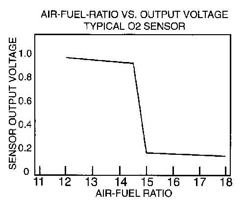
The AFM also has an air temperature sensor that is read by the ECU. The amount of oxygen in the air is proportionate to the density which is proportionate to the temperature. The ECU adds more fuel when the air is colder and denser to maintain the correct ratio of fuel to oxygen. The ratios of air to fuel are commonly set between 12:1 and 15:1. Note: the ECU only adds extra fuel when the incoming air temperature is 20°C (70°F) or less.
A safety switch is also included in some 280z AFM's (75 to early 77 click here to learn more about fuel cut off) . When the engine is stopped, the flap is closed. A switch senses that the flap is closed and turns off the fuel pump. The primary function of this feature is to prevent fuel being pumped when a car crashes. Note: some 280z's have a second wire from the oil pressure sensor that controls fuel cut off in place of the AFM switch.
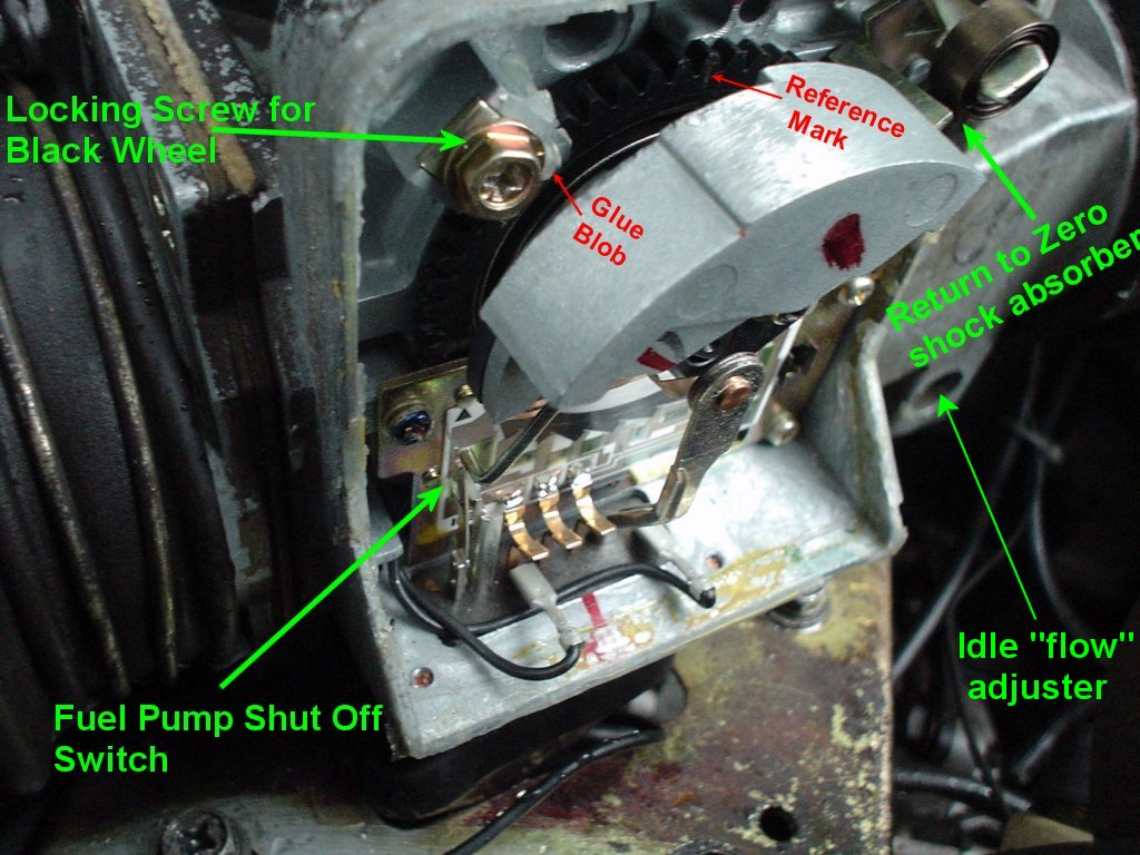
Picture 1
FEATURES IN Picture 1:
The big grey chuck of metal is a counter balance weight. It is used to offset the weight of the wind vane "flap" in the air path to allow for easy rotation by low air flow..
The "Return to Zero Shock Absorber" is simply spring metal that absorbs the shock of the rotating Counterweight and Flap when the air flow stops. It prevents the AFM from beating itself to death every time the engine is stopped.
The Black Wheel and Coil Spring is the mechanism that controls how far the flap opens when air flows through the throttle body. This is the heart of the AFM and if the spring is set incorrectly, the related voltage to the ECU will be wrong and it will send too much or too little fuel. If the spring is wound too tight, the AFM's flap will not move enough and the ECU will not send enough fuel thus a lean mixture will occur. If the spring is wound too loose, the AFM's flap will move too much and the ECU will send too much fuel thus a rich mixture will occur.
IT IS IMPORTANT TO POINT OUT THAT THE BLACK WHEEL IS UNDER TENSION AND THAT REMOVING THE LOCKING SCREW WILL RESULT IN IT GOING "SPRONG" and RECOILING.
BE SURE TO MARK A TOOTH PRIOR TO TOUCHING THE LOCKING SCREW!!!! Besides I have not got to that step yet so hands off!! :)
You will also notice a blob of silicone or glue. If this is broken, you can immediately determine that the AFM was "messed with". Upon inspection of my 77z, the previous owner had obviously turned the black wheel about 10 tooth-steps to the lean side as a smaller part of the blob had been separated and was ~ 10 teeth to the right.
Please note the reference mark that I scribed into the black wheel. It is impossible to see but there is a corresponding scribe mark in the cast metal body as well. (It is good to have both wheel and body scribed in the same location. Preferably at the centre of a tooth.
Idle Flow Adjust
This allows you to tweak the position of the AFM flap at idle thus you can control the rich/lean mixture. This adjustment controls the air flowing around the flap in a "bypass" passage under the AFM's main passage. It works in a similar fashion to the idle set screw in the throttle body.
Click to read an interesting Air to fuel Ratio Blurb by Ian Staunton
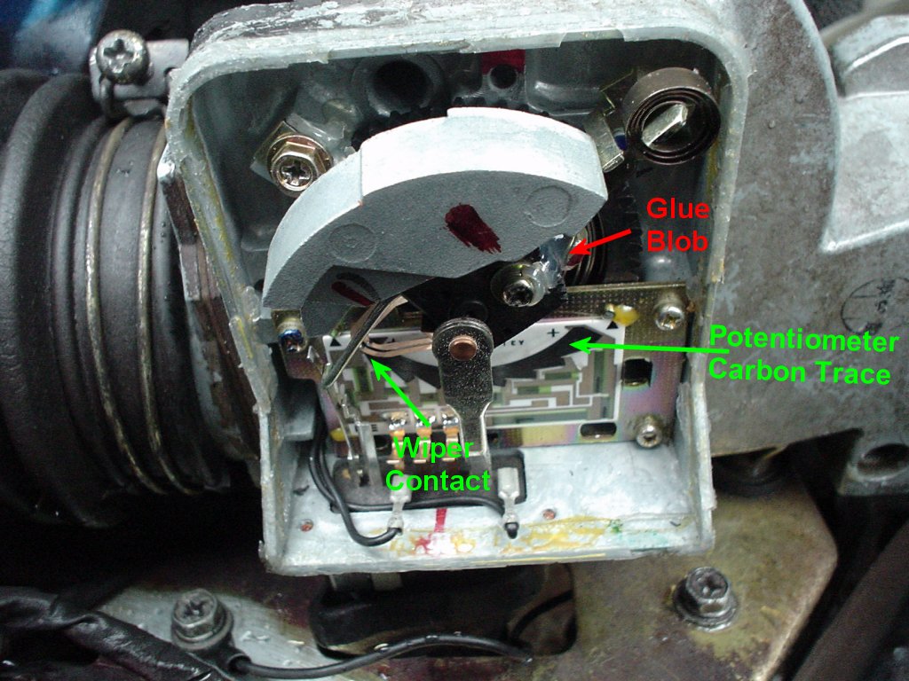
AFM Parts (more)
Here you can see a few more features/parts and some of the previous parts in more detail.
Potentiometer Wiper. It contacts the carbon trace and sweeps a path along it as the flap is moved. It "sends" the corresponding voltage that it "picks up" from the carbon trace".
Carbon Trace. This is the resistive element that divides the voltage. As the wiper travels along it, the corresponding voltage is picked up from approximately 2V to 7V. it is interesting to note that the ECU also measures the resistance across a "reference' resistor in the AFM. Since resistance changes with temperature, any resistance changes in the primary carbon trace can be compensated for by the same amount measured in the reference resistor.
Glue Blob #2. The related locking screw allows you to set the wiper to the 0V position when the flap is closed. It also allows you to adjust the Fuel Pump Cut-Off Switch actuator (silver nail-like arm).
With the AFM in the off position, the "Return to Zero" shock absorber spring should be resting against the rotating weight assembly. (Mine was bent back and not touching... possibly from age or from an explosive "front fire" that slammed the AFM flap shut from behind... anyway I simply bent it back into place. When the Assembly Returns to Zero, the spring metal shock absorber contacts ~ 1/2 cm before the assembly hits the stop.
Inspection Time:Remove the AFM from the car (remove the two rubber hoses.. careful not to rip/stress and the four bolts on the bottom plate... note the ground strap...also DISCONNECT THE BATTERY -NEG terminal and unplug the connector to the ECU )
With the AFM on your lap, verify that the return to zero shock absorber is doing it's job. If not, do the obvious to "make it so" said Picard. Gently bending the metal is all that may be needed (look at the next slide to see how the shock absorber should be set up).
Inspect the Flap and make sure it moves freely. Check for damage, tight spots, and play.
Inspect the Fuel cut off switch and ensure the contacts are physically making and breaking when the AFM is in the "off" mode.
Inspect the wiper and ensure it is contacting the trace at the most clockwise (CW) end. Actually it should stop about 2 to 4 mm from the end of the carbon trace and not run off it)
(My AFM had the wiper shooting too far CW and it was off the trace and registering "open" on a volt meter. I had to loosen the second locking screw near the centre of the assembly (not the black wheel one but rather the "black arc/pie" one and move the wiper as well as the silver arm that activates the fuel pump shutoff switch... play with it gently and you can figure it out)
Also inspect the wiper to carbon trace contact point as the wiper is swept along the trace (move the flap to make it travel)
CLEANING TIME:Use a good quality switch/contact cleaner such as Caig "Deoxit"
Clean the Fuel Pump Switch Contacts
Clean the wiper and carbon trace
Clean the multi-pin conductor contacts
MEASUREMENT TIME!!Now for some multimeter measurements at the connector.
Measure the resistance across the Fuel Shut off Switch (Pins 39 and 36). Move the AFM flap and ensure the resistance is infinite when the flap is closed and quickly changes to 0 ohms when the flap starts to open.
Measure the resistance from the high side to the low side of the pot/copper trace. (Pins 8 and 6). It should read ~180ohm
Measure the resistance across the "standard"/"Reference"/"Control" resistor. (Pins 8 and 9). It should read 100ohms
Measure the resistance across pins 7 and 8 while moving the flap. It should change. (though it may be jumpy)
Repeat this but between pins 6 and 7 while moving the flap.
Measure the resistance of the thermal sensor. It should read 2500ohms +/-250ohms@ 68°C
Fingering
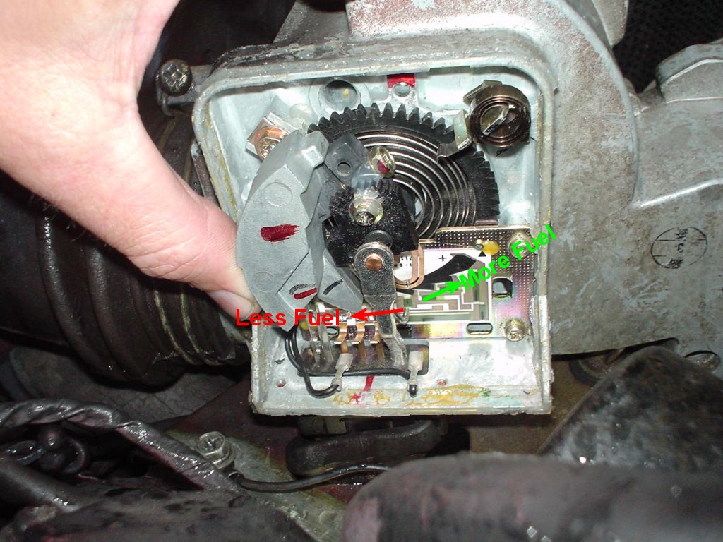
Picture 3
Now to see if the AFM needs to be adjusted.
IT IS IMPORTANT THAT THE FOLLOWING ITEMS ARE CHECKED TO BE FUNCTIONING PROPERLY AND CONFIGURED PROPERLY PRIOR TO CHANGING THE AFM SETTINGS AS THE AFM MAY SEEM TO MAKE AN IMPROVEMENT BY COMPENSATING FOR ANOTHER PROBLEM THAT IS MASKED. TAKE THE TIME TO DO THE FOLLOWING CHECKS:
IGNITION TIMING. Set it to factory recommendations on the hood label. If the timing is too advanced, the engine may have "lean" symptoms that will be incorrectly compensated by pushing the AFM towards the rich side. This will result in two devices that are configured incorrectly.
MECHANICAL TIMING. Check the timing chain and ensure the cam is synchronized with the crank. Check the valve lash.Check all 6 spark plugs and verify they all have same colour.
All OTHER COMPONENTS OF THE FUEL INJECTION SYSTEM: A leaky cold start valve will make the engine run richer. This can be incorrectly diagnosed and compensated by an AFM adjustment thus again you are worse off as two components are configured incorrectly. Likewise the temperature sensor in the AFM could be faulty and cause the ECU to bias rich. A Thermotime switch can stick causing the mixture to be rich, a fuel injector could leak causing a rich burn in one cylinder and cause black smoke. High fuel pressure could result in more gas squirt in the cylinders and a rich mixture. Low fuel pressure or dirty injectors could make a lean mixture. The connections to the temperature sensor in the thermostat housing (or on side of head for CHT) are notorious for causing a *very* rich mixture when they disconnect or corrode.... etc. Just do yourself a favour and download the FI bible (get it here) and do a once over the FI system before attacking the AFM. Also ensure all electrical connections within the EFI system are good (typically they are tarnished or green with oxidized copper.. simply clean them with isopropyl alcohol and a small file or electrical contact cleaner).
VACUUM LEAKS: Air entering the manifold through a ripped boot, broken hose, disconnected hose, poor gasket seal (such as the valve cover gasket or intake manifold gasket), or faulty pollution control device will actually bypass the AFM thus it will not be measured. The ECU will not know about the extra air entering the combustion chamber. Had the correctly air passed through the AFM, it would have forced the AFM flap higher and the ECU would have sent more fuel. These leaks will result in a lean mixture.
Valves Adjusted: Incorrectly set valves can give false lean/rich symptoms and poor performance that can be masked by an AFM adjustment.
FINGERING CHECK:
This check is manually simulating an AFM adjustment without actually releasing the black wheel. Simply moving the AFM wiper/weight assembly to-and-fro while the engine is running will allow you to hear an improvement in engine functioning.
The method is very simple:
Remove the black plastic AFM cover.
Start the car in neutral with hood open and let it warm up.
While idling, the AFM flap will have opened slightly and the wiper will be approx 1cm from it's off location.
Gently and slowly rotate the wiper counter-clockwise towards the rich side (MORE FUEL) side. Listen to the engine and see if it runs stronger and better.
Gently and slowly rotate the wiper clockwise towards the lean side (LESS FUEL) side. Listen to the engine and see if it runs stronger and better.
Decide if the engine runs better with more or less fuel.
Press on the linkage to the throttle body and hold the engine steady ~ 3000rpm.
Gently and slowly rotate the wiper counter-clockwise towards the rich side (MORE FUEL) side. Listen to the engine and see if it runs stronger and better.
Gently and slowly rotate the wiper clockwise towards the lean side (LESS FUEL) side. Listen to the engine and see if it runs stronger and better.
Verify that the direction and amount of movement needed to improve the engine performance is approximately the same at idle and at 3000rpm.
If the amount of movement to improve the performance seems significant, and/or you have "broken glue glob" evidence of previous tampering with your AFM or you simply want more performance, then go to the next image and follow the instructions.
Note: My calibrated stock AFM requires a fingering movement of ~ 4mm to the right (rich) to make maximum rpm when fingering. You may wish to tune your AFM to this point rather than at the maximum rpm point from fingering. Please refer to this better method of setting up your AFM (click here)
If you feel motivated, also check at higher rpms.
Picture 3 Reference Tooth Marked
AFM ADJUSTMENT FOR
MAXIMUM POWER
NOTE: DOING THIS CORRECTLY OR INCORRECTLY CAN POSSIBLY CAUSE PROBLEMS. DO SO
AT YOUR OWN RISK.
Scratch a reference mark on a tooth and also on the metal AFM case. If anything fails, you can always return to these original settings. (DO THIS !!!!)
Finger the AFM while holding the throttle near idle, in middle and near WOT.
if fingering the AFM's wiper assembly CW improves performance performance then the spring was too loose and allowing the ECU to send too much fuel. (go to step 3)
if fingering the AFM's wiper assembly CCW improves performance then the spring is too tight and is preventing the ECU from sending enough fuel. (go to step 4)
To adjust the AFM so that
it adds less fuel, simply pull to rotate the counterweight to
expose the locking screw for the black wheel. Press firmly against the
black wheel to prevent it from recoiling and loosen the locking screw
(the one in the upper left in the photo).
Carefully rotate the black wheel forward (CW) ~4 teeth
steps (while maintaining finger pressure) and retighten the locking
screw.
To adjust the AFM so that
it adds more fuel, simply pull to rotate the counterweight to
expose the locking screw for the black wheel. Press firmly against the
black wheel to prevent it from recoiling and loosen the locking screw
(the one in the upper left in the photo).
Carefully rotate the black wheel back (CCW) ~4 teeth steps
(while maintaining finger pressure) and retighten the locking screw.
Run the engine and repeat the above steps 2 to 4 until you are happy. Note: your AFM's final tooth setting should be relatively close to the original marked setting.
Read plugs and clean.
Drive at least 10 miles and check plugs to ensure you are not too rich.
AFM ADJUSTMENT FOR FUEL
EFFICIENCY
NOTE: DOING THIS CORRECTLY OR INCORRECTLY CAN POSSIBLY CAUSE PROBLEMS. DO SO
AT YOUR OWN RISK.
Scratch a reference mark on a tooth and also on the metal AFM case. If anything fails, you can always return to these original settings. (DO THIS !!!!)
Run a full tank of gas and measure MPG. (Top up tank to 3" below filler neck vent, reset trip odometer and drive for 300 miles, fill up tank again to to 3" below filler neck vent, note fuel dispensed at pump, divide this by 300 miles or whatever is on the trip odometer to get MPG).
Finger the AFM while holding the throttle near idle, in middle and near WOT.
if fingering the AFM's wiper assembly CW improves performance performance then the spring was too loose and allowing the ECU to send too much fuel. (go to step 4)
if fingering the AFM's wiper assembly CCW improves performance then the spring is too tight and is preventing the ECU from sending enough fuel. (go to step 5)
To adjust the AFM so that
it adds less fuel, simply pull to rotate the counterweight to
expose the locking screw for the black wheel. Press firmly against the
black wheel to prevent it from recoiling and loosen the locking screw
(the one in the upper left in the photo).
Carefully rotate the black wheel forward (CW) ~4 teeth
steps (while maintaining finger pressure) and retighten the locking
screw.
To adjust the AFM so that
it adds more fuel, simply pull to rotate the counterweight to
expose the locking screw for the black wheel. Press firmly against the
black wheel to prevent it from recoiling and loosen the locking screw
(the one in the upper left in the photo).
Carefully rotate the black wheel back (CCW) ~4 teeth steps
(while maintaining finger pressure) and retighten the locking screw.
Run the engine and
repeat the above steps 2 to 4 until you are happy that you are in
the maximum power range. Note: your AFM's final tooth setting should be
relatively close to the original marked setting.
Mark the maximum power
tooth with an "X" then rotate the black wheel ~ 4 to 6 teeth CW.
Run a full tank of gas
and measure MPG. (Top up tank to 3" below filler neck vent, reset
trip odometer and drive for 300 miles, fill up tank again to to
3" below filler neck vent, note fuel dispensed at pump, divide this
by 300 miles or whatever is on the trip odometer to get MPG). You should
be ~ 23-26mpg (US Gallon).
Read plugs and make sure you are not too lean.
If you are really keen you may recall that I mentioned a "separated
blob of glue". Well by rotating the wheel, I could reform the original
blob and regain the factory settings. It was ~ 2.5-3 teeth leaner than my
optimal power setting.
I ran each setting for ~ 4 days each.
For the lean factory setting, I obtained 23mpg
For the rich power setting, I obtained 19mpg but had more fun!!!
I hope this information helps you understand the AFM better!!!
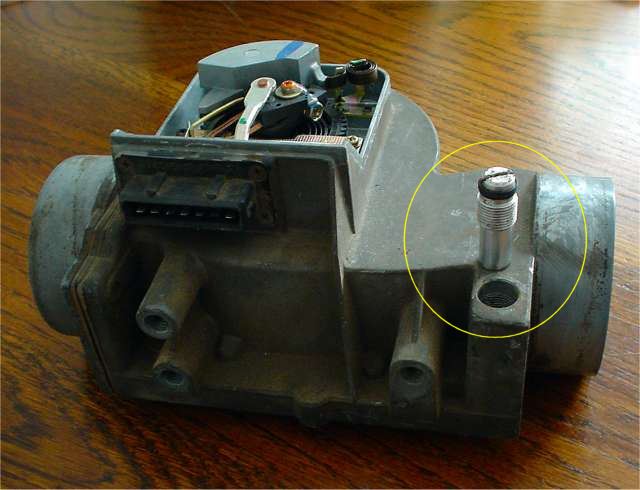
Here you can see the AFM bypass adjustment screw. It
is used to close a passage under the primary AFM passage.
This passage is primarily used to vary the air to fuel ratio at idle. The screw
controls how much "extra air" bypasses the AFM.
Closing passage is accomplished by turning the screw CW.
btw When the intake "pops" aka front fire usually due to running
lean;. the energy passes through this passage.
If it is closed off, the energy will damage the flap.
AFM Water Calibration