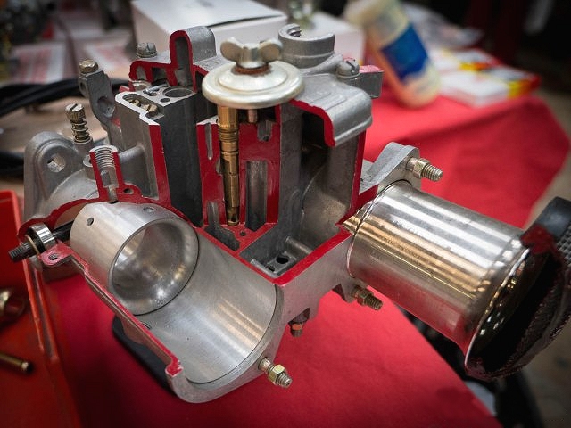
Figure 0. Weber DCOE Cut Away
By: Philip Pilgrim
Weber DCOE Carburetor Reference: Theory,
Configuration, Tuning, Modifications, & Reference Documents
(for Datsun 240z, 260z, & 280z Owners)
Thanks to Weber Expert Dave from
CarbParts.eu for
continued technical oversight
![]()
Figure 0. Weber DCOE Cut Away
By: Philip Pilgrim
Contents:
1. Introduction
2. Theory of Operation
3. Circuit Drawings
4. Components
5. Tuning
6. Rebuilding
7. Modifications
8. Racing
9. Reference Documents
1. Introduction:
More Complex than an SU:
The SU carbs on our early Datsun 240z's & 260z's are
constant velocity carbs that have only one circuit that meters air and
distributes fuel. It is a simple design with a clever automatic method that
exploits a movable piston and needle valve. This one circuit works across the
full rpm range and full load range from idle to wide-open-throttle (WOT).
In contrast, the Weber DCOE is more complex in that
it has five separate circuits whose components are fixed. These circuits are
optimized for different parts of the rpm range and load range. These circuits
interact and overlap at the transitions in rpm and load. Unlike the SU that uses
a big clunky piston, the DCOE's metering of fuel is based upon small precisely
machined brass jets that are well fixed inside the carb. They are very capable
of working in in high g-force racing conditions and a wide selection of jets and
other parts allow for the DCOE carb to be optimized for nearly any engine size
and application.
Enjoy this Refreshment Before Continuing to
Read:
Remember: The pistons are trying to pull air into the engine
like lungs breathing. Your foot on the accelerator pedal only lets air into the
engine (It is not a "gas" pedal but rather an "air" pedal). Your foot is
controlling how much air enters the engine by opening and closing a throttle
valve. The carburetor's job is simply to mix the correct quantity of fuel with
the air you let pass through it so that the engine can burn it correctly. The
carb has to correctly add the right amount of fuel for all situations: cold,
hot, travelling over violent bumps, when pulling high g-forces:
turning/braking/accelerating, with engine vibrations, when idling, when
racing, when cruising through town or along a highway, when operating high in
the mountains or at sea level.
Why this Page Exists:
Having tamed the DCOE beast, I will attempt to pass
along my findings to help you confidently do the same but with fewer obstacles. In retrospect, DCOE carbs
are fairly easy to understand and easy to set up. The challenge is to have
someone reduce the beasties to the simple elements for which they actually are....
thus this page.
It's Simple:
Weber DCOE carbs have always carried an air of a
mystery in their operations and tuning. They have been with us for many years,
(DCO's since the early 1930's). Still, after 85 years, it is as if there is some sort of magic associated
with DCOE's and with anyone who can tune them. This is false. They are simply
lumps of aluminum composed of a handful of sub-sections (circuits) that can all
add fuel at different times during the operation of a vehicle.
Each of the circuits can be "tuned" by replacing components (typically changing
items with different sized holes to let more air or fuel into each circuit...or
to reduce air or fuel in each circuit).
The correct interworking of all circuits together is the ultimate goal of a
properly tuned DCOE. However, one must be careful as the circuits overlap one another; it is possible to
sometimes fix an over-fuel situation in one circuit by under-fuelling in another.
Beware of the Internet: (but not this page)
Often many of us go down the path of seeking ideal
configuration advice on the internet. This is difficult to do and
usually leads one down the wrong path (loss of performance, running too rich,
etc.). The problem is that most proclaimed configurations are from un-vetted
sources promoting certain settings and component vales that are not accurately
verified and most often, subjective. Furthermore, if the engine with the
promoted settings is not the same as yours then the settings are moot. A good
example of this problem is that most proclaimed "ideal" settings do not include
fuel level. This one critical factor will greatly skew how all of the circuits
work. If your fuel level is different from the person's promoting the ideal
settings, then you are wasting your time copying their settings. In fact this
problem happened to me. When I first started to tune DCOE's for a 240z, I
thoroughly read a very long DCOE configuration thread on a website forum called
HybridZ. I wrongly assumed most of the posts were accurate and from experienced
DCOE tuners. It was a waste of time (Out of curiosity I just looked and the
continuing thread and it is now over 800 posts of the blind leading the blind!).
Their settings did not work for me and after I paid my dues in learning the DCOE
circuits and the DCOE circuit interactions, I can now see how most of the
HybridZ DCOE content is incorrect and I can advise not to try to mimic the
settings and advice of others. If the "internet" DCOE settings do not state the
fuel level and DCOE version along with engine displacement, manifold, tuning,
etc. then they are not useful.
Having stated the least favourable way to configure
DCOE's, the ultimate way to configure and optimize DCOE's is to set up the
engine on a dynamometer and tune for power or fuel efficiency, or whatever your
goal is. This has been done many times and ideal values achieved.... however
this is usually expensive and done on race motors by race teams for maximum
performance and least risk of damage in contingencies. Most of us do not have
race motors let alone race so again, their optimized DCOE configurations are
usually not the same as ours.
Since most of us have street machines and most of us
do not have engine dynos, we are forced to tune by simply driving.
The first step to tuning Weber DCOE's is to understand
how they work and their various circuits.
2. Theory of Operation
This section is an attempt simplify and present DCOE functioning so that you can
quickly grasp the basic concepts.
It is a fictional guess at how Mr. Weber would have developed a DCOE design
step-by-step. It should help in demystifying the DCOE:
The Ideal:
The simplest carburetor design would be a tube to flow
air with a source of gasoline spraying in the centre of the tube. This would
provide even distribution and symmetrical mixing of air and fuel at the highest
velocity point of the tube.
Figure 1. Ideal Carb
Approaching the Ideal:
The DCOE Main Circuit
The Weber DCOE side-draft carb, commonly used on the
Datsun 240z, 260z, & 280z, is basically just a tube with a fuel nozzle in the
mid-stream of the air path.
In Figure 2, the DCOE Main circuit is shown. It is very much like the Ideal Carb
above.
Figure 2. DCOE Main Circuit
Unfortunately another part was
required.... the Throttle Valve. It is connected to the accelerator pedal and
controls the amount of fuel and air drawn into the engine. Its location was
chosen to be downstream from the fuel nozzle as the manifold vacuum on the motor
side of this valve would otherwise suck the fuel from the fuel nozzle when the
throttle valve was closed. The main drawback of the throttle valve location
being downstream is that it still blocks the air flow when open and, fuel sprays
over it and can also be deposited on it. In addition to a simple tube with a
fuel nozzle design, Weber shaped the tube so that it was narrowest where the
fuel was drawn into the air stream by using the Venturi principal. This promoted
fuel draw and fuel distribution.
Here is a nice video showing the DCOE main circuit flowing water on a flow
bench:
Video 1. DCOE Main Circuit "Wet Flow"
The DCOE carb has many swappable parts for the main circuit to configure it for
different engine sizes and applications. These will be discussed later. For the
present, just focus on the theory of operation.
Side Note: It is interesting how this simple tube
and nozzle design is nearly identical to a modern high performance fuel injected
individual throttle body (ITB) manifold architecture. Modern fuel systems
actively squirt fuel in precisely metered quantities into the air stream where
as carbs must draw the fuel through Venturi vacuum created by the air stream.
The above Main Circuit design is only marginally optimal for being an Ideal
Carb. It works OK in the middle to wide open throttle range yet it fails
completely at idle and works poorly at WOT.
Here are the two main deficiencies of this simple
design:
1. At lowest rpms (Idling) when the throttle
valve is nearly closed, there is not enough air flow over the main nozzle to
draw fuel. (Lean)
2. At higher rpms when the throttle valve is
moderately to fully opened, the air fuel mixture becomes too rich as too much
fuel is drawn from the main nozzle. (Rich)
Reality and Corrective Actions In the Design:
Adding the Idle Circuit and the Emulsion Tube
The way the DCOE addresses the above
two problems of Main Circuit fuel flow at both ends of the RPM spectrum is:
The DCOE Idle Circuit:
To address idling lean, as the main nozzle is situated nowhere near the high
velocity air flow, a separate second circuit is added: the Idle Circuit (Figure
3). It is simply a variable hole (needle valve) on the high vacuum downstream
side of the throttle valve. This needle valve independently controls the amount
of pre-mixed fuel and air (mixed upstream and not shown for simplicity) to flow
past the throttle valve and feed the engine when the throttle valve is nearly
closed (and the main circuit was not functioning due to low air flow). The
simple one circuit carburetor example now becomes two circuits (Main and Idle).
As with the DCOE Main Circuit, the DCOE Idle Circuit has configurable parts that
can be swapped to adapt it to different engine sizes and applications. Details
will be shown later.

Figure 3. DCOE Idle Circuit
The Emulsion Tube:
To address the need to lean the mixture in the Main Circuit as the throttle
valve approaches "Wide Open Throttle valve" (WOT), a “fuel/air mixing tower” is
added. It is a tube with holes in it and it is called an “emulsion tube”. Air
and Fuel mixing takes place in and around this tower before the fuel/air
emulsion is drawn
out of the assembly. Fuel enters the tower at the bottom of the well and air
enters from the top. As the fuel demand increases approaching WOT, the fuel
level in the tower & well lowers and in turn, exposes more air holes thus mixing
more air with the fuel. This ultimately leans the mixture (as required) in the
main circuit as more airflow through the carb occurs.
Here is a picture of a DCOE emulsion tube and a video of it in action mixing air
with fuel as a stationary car is rev'd to WOT (with no load). Details of the emulsion tube will be shared
later in this page. Currently the main point to take-away is that the emulsion
tube and well prevents the Main Circuit from going too rich at WOT by mixing air
with the fuel.
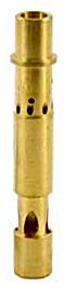
Figure 3. DCOE Emulsion Tube
Video 2. DCOE Emulsion Tube Mixing Air with Fuel for Main Circuit
Note: The fuel level is too high to start and it creeps higher.
Video 3. DCOE Main Circuit Operating
Note: The emulsion tube is not optimal or the fuel level is too high as pure gas
dribbles out when the main circuit is first activated. This common problem will
be addressed in the tuning section.
To recap: The DCOE has been
shown to be at least a 2 circuit carb design:
One being the Idle Circuit and the second being the
Main Circuit.
....But how to switch from one circuit to the other circuit slowly and quickly?
Dealing with the Transitions: Adding
the Progression Circuit and the Acceleration Circuit
The DCOE Progression Circuit (for slow
transitions from Idle Circuit to Main Circuit):
As the throttle valve slowly opens, when transitioning
from the Idle Circuit to the Main Circuit, the air flow required to activate the
main circuit does not occur quick enough. This delay in the main circuit
starting causes a lean spot between Idle and Main. The solution is to simply add
more fuel holes near the throttle valve. These holes are drilled upstream of the
idle needle valve port. As the throttle valve is opened, it exposes each
successive hole to the manifold vacuum and air flow. In turn, (due to high
velocity air and manifold vacuum) it draws more mixed air/fuel from each
progression hole. For economy of design, the source of the air fuel used in the
Progression Circuit is simply a tap from the Idle Circuit.

Figure 4. DCOE Progression Circuit
It is important to note that
when cruising down the highway at constant speed, the throttle valve is usually
opened only part way between idle and WOT thus the Progression Circuit is
important for cruising performance (static) and when transitioning from idle
towards WOT (dynamic).
It is *very important* to note that the Progression
Circuit is fed fuel and air directly from a configurable part in the DCOE called
the Idle Jet. The only way to adjust the air and fuel in the progression circuit
is to swap the Idle Jet with others of different sizes or to raise and lower the
fuel level. In fact, to better understand the DCOE carburetor, renaming the
"Idle Jet" to the "Slow Progression & Cruise Jet" would be more intuitive. The
Idle Circuit is more or less dependent only on the Idle Enrichment Screw.
The Accelerator Pump Circuit (for fast
transitions from Idle to Main):
If the throttle valve opens quickly (when
transitioning from the Idle Circuit to the Main Circuit) the Progression Circuit
above does not have enough time to operate as the airflow is suddenly
distributed across the whole carb throat rather than focused up near the roof
and progression holes. This sudden bust of air and delay in the main circuit
starting causes a momentary lean spot between idle and main. Most Weber
aficionados call this the "gasp". The solution is to
actively add more fuel by using a one-shot-squirt-gun-like pump that is
activated on a quick throttle opening (hammering the gas pedal). The Accelerator
Circuit design also had a clever feature where slow throttle valve openings do
not squirt additional fuel (to be shown in more detail further below).
The Accelerator Pump actively and forcefully squirts fuel into the air flow like
a fuel injector but it does so only for 1 shot.
As with the other circuits, The DCOE carb has swappable parts to configure the
accelerator circuit for how much fuel is squirt and for how long.
Figure 5. DCOE Accelerator Circuit
Video 4. DCOE Accelerator Pump "Squirting"
Video 5. DCO Main and Accelerator Pump (Too Rich)
Summary to this Point:
A Weber DCOE side draft carb used on many Datsuns now
has at least four independent "circuits":
1. Idle Circuit (used at idle)
2. Main Circuit (used between cruising and WOT)
3. Progression Circuit (used to aid in
slow rpm
transitions from Idle Circuit to Main Circuit and to provide most fuel at
cruising).
4. Acceleration Circuit (used to aid in
fast
rpm transitions from Idle Circuit to Main Circuit).
Figure 6 is a graph showing the three passive
circuits (Idle, Progression and Main) and how they overlap across the engine
RPM's. This will be an important point to note when tuning the DCOE carb.
The Acceleration circuit is not shown as it is active and only squirts when the
accelerator pedal is pushed quickly.
Figure 6. Overlap of DCOE Circuits and RPM
The Starter Circuit
(for cold starting):
The final circuit (the fifth) in the Weber DCOE is the Starter Circuit. It is an
optional circuit that is not present on many DCOE's. It is not needed for race
applications and it is not useful for most climates. In fact it can be a
nuisance if it malfunctions. Finally, for cold weather starting, simply pressing
the accelerator pedal quickly a few times will squirt fuel into the intake
manifold and prime the cylinders prior to ignition. This priming is a good
substitute for the Starter Circuit.
Well I guess I should say something about the Starter Circuit! It is not at all
like a Choke. It is very complicated and is much like a little carb within a big
carb. It has its own fuel and air passages and components independent of the
other circuits. When active, it feeds fuel downstream from the throttle
plate so it is exposed to manifold vacuum (just like the idle enrichment screw).
As with the other DCOE circuits, the
Starter Circuit has many swappable parts to enable configuring it for many
different engines.
It is confusing as to why this circuit is so complex and configurable for automotive applications,
however, Weber carbs are used for many applications and it may be for cold
weather vehicles or cold weather marine applications.
Figure 6. DCOE Starter Circuit
The Fuel Bowl:
Although the fuel bowl is not a "Circuit" in the Weber DCOE. It is common to all
circuits and deserves special mention:
Like most carbs, the Weber DCOE has a fuel bowl from which fuel is used for the
five circuits. Apart from the active Accelerator Circuit, the remaining
four circuits are passive and fuel is drawn from the fuel bowl through vacuum.
Both manifold vacuum and Venturi vacuum pull the fuel up from the fuel bowl.
The fuel level greatly affects how much fuel is drawn into each circuit for the
same amount of vacuum (air). The higher the fuel level fuel, the more of it will
be drawn and the richer the mixture becomes. Fuel level is critical for
correct running DCOE carbs. A high fuel level will bring the main
circuit in too early and over power the progression circuit to make cruise
"stinking rich". The high fuel level effectively hampers the correct functioning
of the emulsion tube by flooding the upper holes.
Like other DCOE parts, fuel bowl related components are configurable with
interchangeable parts to adapt to a variety of engines. br />
3. Circuit Drawings
This section contains drawings of Weber DCOE carbs and highlights the various
circuits.
Air & fuel passages and mixing is shown by colour. Air is blue and fuel is
yellow. Mixed air and fuel is green.
Idle Circuit Drawings

Figure 7. DCOE Idle Circuit Flow & Components
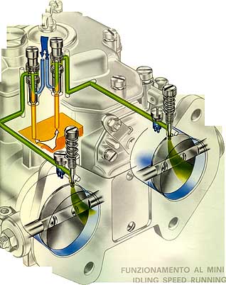
Figure 8. DCOE Idle Circuit
Flow
(Higher Resolution) Note the narrow-taper Idle Enrichment Screws.
Figure 9. DCOE Idle Circuit (Side View) Note the
wide-tapered Idle Enrichment Screw.
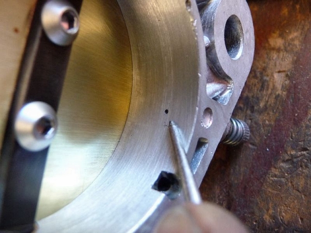
Figure 11. DCOE Idle Enrichment Hole
NNote that the Idle Enrichment
Hole is on manifold vacuum side of the throttle valve and is subjected to a
large pressure difference that pulls the air/fuel mixture from this hole. Some
air also flows past the throttle valve at idle to dilute this mixture.
![]()

Figure 12. DCOE Idle Enrichment Screws (Two common types shown above with different
tapers however at least six existed as part numbers end with: 1,3,11,23,56,58)
DDCOE Idle Enrichment Screws control how much fuel & air is fed to the engine at idle. At idle the Throttle Valve is opened just a crack so some additional air passes it and also feeds the engine at idle. The amount of fuel and air they provide is generally measured by how many turns out from full close they are set. Early DCOE Webers had a fat wide taper and permitted more flow at smaller turns, later model DCOE Webers are fitted with narrow tapered screws that are more accurate and require more turns to flow the same amount as their predecessors.
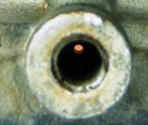
Figure 12a. DCOE Idle
Enrichment Hole/span>
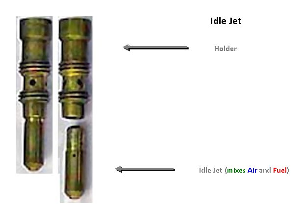
Figure 13. DCOE Idle Circuit Jet & Holder
DCOE Idle Jets meter the amount of air and fuel mixed
and fed to the Idle Circuit & Progression Circuit. The Jets have a fuel inlet
hole at the bottom and air inlet holes on the sides. The mixture of air and fuel
is first pulled through four holes in the holder and then through a complex
winding set of passages in the carb body to reach the Idle Enrichment Hole and
to reach the Progression Holes. Idle jets are available in a wide selection. The
variables are:
1. diameter and depth of the internal cavity
2. diameter of the fuel inlet port
3. diameter and quantity of the air inlet ports
4. diameter of mixture exit port
Main Circuit Drawings
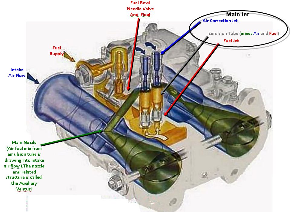
Figure 14. DCOE Main Circuit Flow & Components

Figure 15. DCOE Main Circuit Flow & Components (High Resolution)
Figure 16. DCOE Main Circuit (Side View) Note the inclusion of fuel leaking from
the Accelerator Circuit at WOT.
Video 6. Accelerator Pump Circuit "Leaking" at WOT
(look at the throttle plate at the end of the run to see the raw fuel leak
splash at the top)

Figure 17. DCOE Main Circuit (Front View Showing Venturi, Aux Venturi, & Emulsion Tube)
Fuel is pulled up through the well in which the Emulsion
Tube sits. The fuel travels up both inside and outside of the Emulsion Tube. As
it travels it mixes with air that enters the emulsion tube from the top. The
quantity, shape, location and diameter of holes drilled in the Emulsion Tube
along with its interior diameter and outer diameter affect the mix of the air
and fuel as the engine increases in RPM towards redline. The diameter of the
fuel port in the Main Jet (at bottom) and the diameter of the Air Corrector port
(at top) are also key components in how the emulsion tube works.
It is important to note that the Emulsion Tube only affects the fuel entering
the engine under high loads or high rpms when the main circuit is active. For
most street driving, it is not active. The Emulsion Tube type, Main Jet and Air
Corrector work together to meter the fuel as the rpms rise. They are typically
selected to prevent early WOT lower rpm range from being too rich or too lean
and to prevent the WOT upper rpm range from being too rich or too lean.
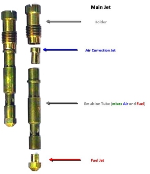
Figure 18. DCOE Main Circuit Emulsion Tube (Parts from bottom: Main Jet, E-Tube,
Air Corrector, Holder)

Figure 19. DCOE Main Circuit Venturi (left) and Aux Venturi 45DCOE (right)
The throat of a DCOE carb has two components along with
a Throttle Valve:
The Venturi (also known as a Choke), is simply a restriction to
reduce the maximum diameter of the throat
(choking it). The Venturi comes in a variety of diameters to help match the carb
to the engine. Smaller engines need less air and larger engines need more air.
The size of the venturi also controls the velocity of the air entering the
engine. Faster flow generally improves low-rpm torque but requires a
smaller diameter choke, higher rpm performance requires the most air flow and a
large diameter choke is usually best. As the main Venturi ultimately
controls the airflow through the carb, all circuits are affected as the flow of
air is what pulls the fuel out of them. Changing the Venturi will require
"re-jetting" (changing the idle jet, main jet & air corrector).
The Auxiliary Venturi is positioned in the centre of the carb
throat where the air velocity is greatest. The Main Circuit dispenses fuel
through it. The Aux. Venturi comes in a few sizes and shapes for tuning.
Progression Circuit
Drawings
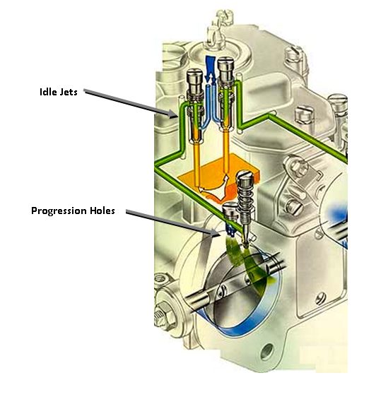
Figure 20. DCOE Progression
Circuit
Figure 21. DCOE Progression
Circuit (Side View)
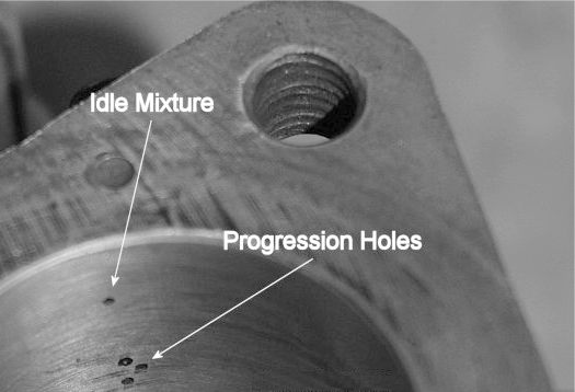
Figure 22. DCOE Progression
Holes
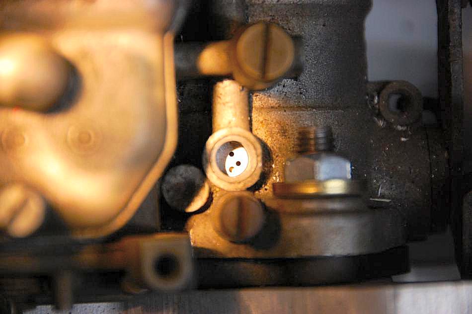
Figure 23. DCOE Progression
Holes (viewed from access port on top)
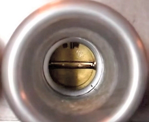
Progression holes can be
viewed from above by simply removing a threaded brass cap (Figure 23). (Note
that some early DCOE's have a non-removable cap so no inspections are possible). This
inspection is important for setting the throttle valve position at idle as it
should be at or behind the first progression hole. In this photo, you can see
that the throttle valve is blocking the first of the three progression holes. It
is a wee bit too far forward as it should only block~ 1/2 of the hole or less.
Getting the Throttle Valve set correctly is an important starting point for
tuning carbs. The design is such that the Progression Circuit should not be
activated until off idle. By having the Throttle Valve set too far forward
when tuning, one can incorrectly select jets that may partially work but the
Progression Circuit will be active at idle and the Main Circuit will come on
early. This will hamper the correct operation and make tuning more difficult
than necessary.
It is also worth noting that different 40DCOE carb bodies have different numbers
of progression holes (ranging from two to four with three being the common).
Size and location of holes also varies. For this reason it is critical
that for multi-carb applications, all carbs are of the same typo and preferably
from the same batch).
Accelerator Circuit Drawings
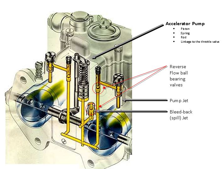
Figure 24. DCOE Accelerator
Circuit
Figure 25. DCOE Accelerator
Circuit (Side View)
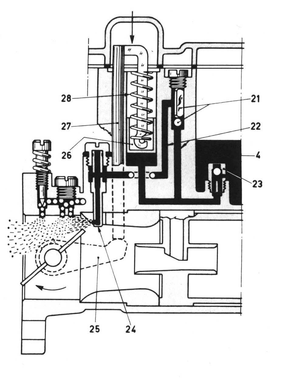
Figure 26. DCOE Accelerator
Circuit (Side View)
The Accelerator Circuit pumps (squirts) fuel when the
accelerator pedal is pressed quickly. It does not squirt fuel when the
pedal is pressed slowly. Special passages and controlled leaks along with a
piston pump are the main components that circulate the fuel. As will other
DCOE circuits, many components are interchangeable with larger and smaller
orifices.
Key points to understand the functioning:
1. The Bleed-Back/Spill jets sit at the bottom of the
fuel bowl.
2. When the throttle valve is closed (idle), fuel
enters the Bleed-Back valve, flows past the ball bearing valve and fills the
pump chamber as the rod is pushing the piston up high in the pump chamber and
the spring compressed. Weights atop the two other ball bearing valves keep them
closed and prevents fuel from flowing out of the two jets.
3. When the throttle is opened quickly, the rod drops
and the spring pushes the piston down. This forces fuel backwards. The ball
bearing in the spill jet is forced upward and closes this valve preventing fuel
from back-flowing into the fuel bowl. The pressure also lifts the other two ball
bearings and corresponding weights (opening these valves) and allows the squirt
of fuel to shoot out each pump jet.
4. The diameter of the pump jet holes, the length of
the piston's excursion, and the spring tension affect how much fuel is squirt
and the time duration of the squirt.
5. When the throttle is opened slowly, the rod also
drops but the fuel squirts slowly back into the fuel bowl as the ball bearing
valve in the bleed-back/spill valve is designed to "bleed" on slow throttle
transitions. In fact the Progression Circuit is designed to be the key supplier
of fuel during slow throttle transitions...however some fuel will inevitably go
through the pump jets. Size of the bleed back valves, accelerator ball bearing
weights and piston spring pressure are the key factors in how "leaky" the pump
jets are in slow to medium transitions and also can be customized for normal
fast transition squirts.
Accelerator pumps are composed of several components:
piston, rod, spring, and retainer:
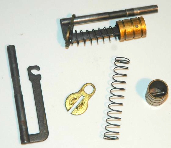
Figure 27. DCOE Accelerator Pump Parts
Rods and springs can come in different sizes:
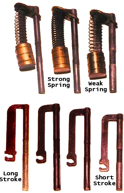
Figure 28. DCOE Accelerator Rod and Spring Selections.
The pump jet. Note the a very
very small washer/gasket accompanies this part and comes with most rebuild kits.

Figure 29. DCOE Accelerator Pump Jet
Back-Bleed/Spill Jet that sits at the bottom of the
fuel bowl

Figure 30. DCOE Accelerator
Spill Jet
Starter Circuit
Drawings
The DCOE Starter Circuit is a Carb
within a Carb. It has its own fuel jet and air jet along with separate passages
in the housing. There are two pistons that are raised and lowered by a cable to
allow the manifold vacuum to draw the fuel/air mixture from the hole in the roof
of the throat. Note: Since the Starter Pistons are on the high vacuum side
of the throttle plate, they can be a cause for fuel leakage. Often they can get
stuck open from carbon deposits.
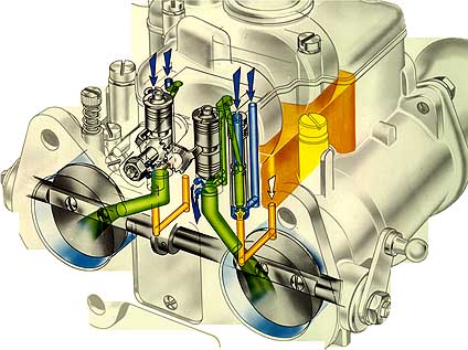
Figure 31. DCOE Starter
Circuit
Figure 31. DCOE Starter
Circuit (Side View)
Figure 31. DCOE Starter
Circuit (Side & Front View)

Figure 32. DCOE Starter Circuit Exit
Most DCOE racing application carburetors have blocking plates instead of a Starter Circuit.
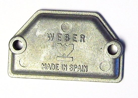
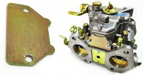
Figure 33. DCOE Starter Circuit
Blocking Plates
4. Components
The Carb Body (Size & Type):
Weber DCOE Carbs have evolved as a device over the past 85 years. They come in a
variety of sizes and series/type.

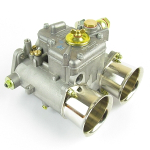
Figure 34. 1931 50DCO
Carburetor and 2016 50DCO
Carburetor
The carbs are identified by the diameter of the throat (in mm), and by the
manufacturing variation. Typical DCOE carbs come in
the following standard throat diameters:
40, 45, 50, & 55. Other throat sizes over the years include 38, 42, 48, 58.
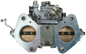
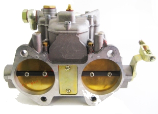
Figure 35. 38DCOE Carburetor
and 55DCO Carburetor
Typical sized carbs for Datsun 240z to 280z with motors
ranging from 2.4liter to stroked 3.4liter range from 40mm to 55mm. The
40mm's make nice street carbs for stock 240z's to 280z's and the 55mm are for racing
applications. A 45mm is a good size to purchase for 280z street applications. It can
cover from 2.8 to 3.4 litres and most additional performance modifications of
these.
40DCOE carbs come a variety of types/variations ("Tipo" in Italian) manufactured
over the years. Variations include number of progression holes (2, 3 or 4),
pattern of progression holes, length of pump rod, progression hole threaded plug
or bronze cap. Here are some Tipos and distinct features:
- 40DCOE-2 (14mm pump stroke)
(float 8.5mm)
- 40DCOE-4
(14mm pump stroke) (float 8.5mm)
- 40DCOE-8
- 40DCOE-9
- 40DCOE-13
- 40DCOE-14
- 40DCOE-15
- 40DCOE-16
- 40DCOE-18 (10mm pump stroke) (float 8.5mm)
- 40DCOE-19
- 40DCOE-22
(10mm pump stroke) (float 8.5mm)
- 40DCOE-23
(10mm pump stroke) (float 8.5mm)
- 40DCOE-24
(14mm pump stroke) (float 8.5mm)
- 40DCOE-27
(14mm pump stroke) (float 8.5mm)
- 40DCOE-28
(14mm pump stroke) (float 8.5mm)
- 40DCOE-29 (10mm pump stroke) (float 5.0mm)
- 40DCOE-30 (10mm pump stroke) (float 5.0mm)
- 40DCOE-31 (16mm pump stroke)
(float 8.5mm)
- 40DCOE-32
(14mm pump stroke) (float 8.5mm)
- 40DCOE-33
(14mm pump stroke) (float 8.5mm)
- 40DCOE-34 (
) (float 8.5mm)
- 40DCOE-35 (
) (float 8.5mm)
- 40DCOE-38 (16mm pump stroke)
- 40DCOE-39 (16mm pump stroke)
- 40DCOE-44 (
) (float 7.0mm)
- 40DCOE-45 (
) (float 7.0mm)
- 40DCOE-62 (16mm pump stroke)
- 40DCOE-63 (16mm pump stroke)
- 40DCOE-68 (16mm pump stroke)
- 40DCOE-69 (16mm pump stroke)
- 40DCOE-70
- 40DCOE-71
- 40DCOE-72 (18mm pump stroke)
- 40DCOE-73 (18mm pump stroke)
- 40DCOE-76
- 40DCOE-77
- 40DCOE-80 (18mm pump stroke)
- 40DCOE-81 (18mm pump stroke)
- 40DCOE-82
- 40DCOE-83
- 40DCOE-84
- 40DCOE-85
- 40DCOE-86
- 40DCOE-87
- 40DCOE-88
- 40DCOE-89
- 40DCOE-92
- 40DCOE-93
- 40DCOE-96
- 40DCOE-97
- 40DCOE-106
- 40DCOE-107
- 40DCOE-149
- 40DCOE-150
- 40DCOE-151
The 151 type is the current commonly available new stock. It has many desirable
features and no wear. It is now manufactured in Spain rather than Italy. The
factory equipment was relocated in 1992.
When selecting DCOE's for your Datsun ensure all three are of the same type and
ideally of the same vintage. Having a mixed set may not distribute fuel evenly
to the 6 cylinders and cause the car to run rougher. It is important to note
that the quantity, size, and location of progression holes varies between 40DCOE
types so this alone will cause fuel delivery differences and difficulties. Mechanical functioning of
the carbs is equally important to ensure they work identically. Different
throttle plate angles and different lengths of the mechanical arms along with
mechanical slop will prevent correct synchronized functioning of the three.
For the best performance, all three carbs should be identical with no mechanical
slop.
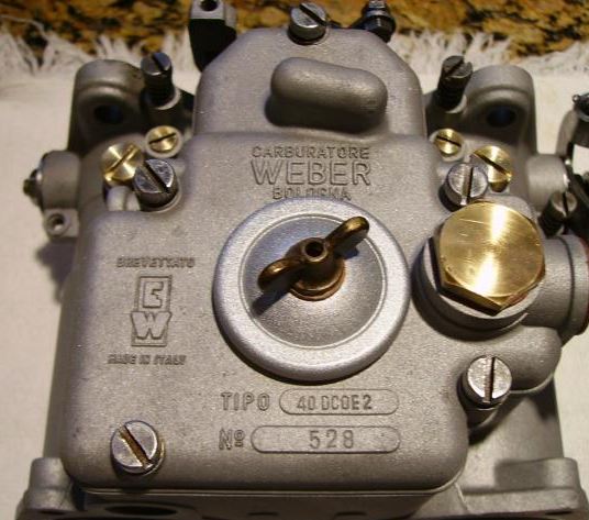
Figure 36. 40DCOE2
Carburetor (Type/TIPO is 2 and stamped on top cover)
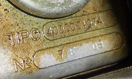
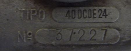
Figure 37. 40DCOE107A Stamp
and 40DCOE24 Stamp
The Venturi (Choke):
The DCOE carb has interchangeable throat restrictors
called Venturi's or Chokes. These devices control the quantity and velocity of
air entering the engine. Generally smaller chokes increase air velocity at low
rpms and improve torque but they eventually become a restriction at higher rpms
and limit maximum power. On the other hand, larger chokes do not work well
at low rpms but they work well at higher rpms. Smaller chokes make street
driving fun. Larger chokes allow race engines to produce maximum power.

Figure 38. A thick-walled
30mm Venturi and a thin-walled 36mm Venturi
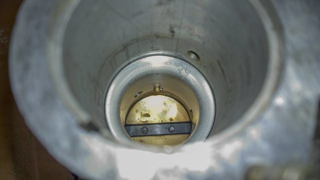
Figure 39. Venturi in Carb Throat
After selecting a carb size for your Datsun, the next step is to select a choke
size. 40DCOE's have a choke selection from 28mm to 36mm, 45DCOE's have a choke
selection from 28mm to 40mm, 55DCOE's have a choke selection from 46mm to 48mm.
Common Weber books recommend 40DCOE carbs with 28mm or 30mm chokes for stock
240z's and 260z's.
Here is data from flow testing 40mm and 45mm DCOE carbs. It appears that a 32mm
choke is the inflexion point where one should consider choosing a 45mm body over
a 40mm body. This would fit well with 280z 2.8l engines and modified 260z 2.6l
engines. One issue raised by Passini is that the sudden throat diameter change
after exiting a Venturi can be very detrimental to the mixture of air and fuel
as it passes. If the cavity after the Venturi is too large, the mixture will
fail and fuel will precipitate. This condition occurs more in 45mm bodies than
40mm bodies for the same Venturi size.
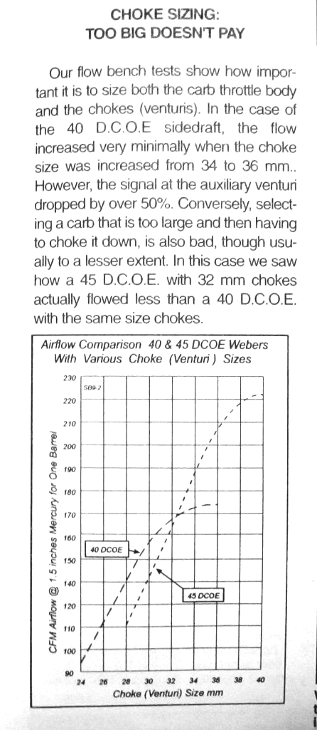
Figure 40. Plot of air flow in 40mm & 45mm DCOE carbs
vs. Venturi/Choke Diameters
From personal experience, a cam'd 2.4l 240z with 30mm
chokes has a very nice low end torque and works well on the street.
For racing, the smallest choke that gives the maximum power on the dyno is the
one to choose.
The Auxiliary Venturi:
The DCOE carb has interchangeable Auxiliary Venturi's.
This device is a smaller venturi whose tail is located in the centre of the main Venturi where
the air velocity is greatest and the pressure is least. Its purpose is simply to
expel the fuel from the Main Circuit into the air stream. The fuel is
pulled out of the main circuit due to the low pressure generated by the
Venturi-in-a-Venturi structure.

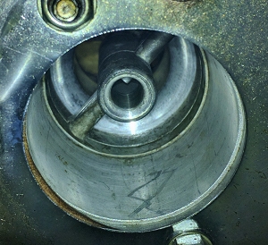
Figure 41. Auxiliary Venturi (part and installed)
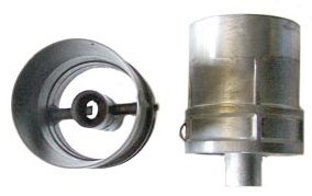
Figure 42. 40DCOE Auxiliary Venturi is just one part.
(The 45DCOE Aux. Venturi is two parts)
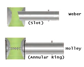
Weber Auxiliary Venturi's come in sizes from 3.5, 4.0, 4.5, 5.0, 5.5, and 6.0mm.
This size is an "equivalent hole diameter that would flow the same amount of
fuel" as the rectangular slot in the Auxiliary Venturi.
Common Weber books recommend 40DCOE carbs with 4.5mm Aux. Venturi's for stock
240z's and 260z's.
For racing applications, use the smallest size that provides maximum power on
the dyno.
The Idle Jet:
The Idle Jet is inappropriately named as it primarily
controls the cruise mixture more so than the idle mixture. In fact, the Idle
Enrichment Screw directly controls the idle mixture. The Idle Jet simply
feeds it.
When cruising along a street or highway in a Datsun, the Progression Circuit is the main
contributor to the mixture entering the engine. Only the fuel level and
Idle Jet are at play. It is very important to select the correct Idle Jet and
set the correct fuel level in a DCOE carb so that a suitable air/fuel ratio at
cruise is obtained. In the tuning section below, selecting the correct
Idle Jet at cruise will be the first
and most crucial step. The mixture at cruise can not be tuned by the main
circuit nor can it be significantly tuned by the Idle Enrichment Screw.
The cruise mixture must be set by selecting the correct Idle Jet AND by setting
the correct fuel level.
The Idle Jet

Figure 43. Idle Jet and Holder
The Idle Jet mixes air and fuel inside its drilled cavity. Fuel enters from the
bottom and air enters from the side. The air/fuel mixture is drawn out of the
top of the jet and then through four holes in the side of the holder.
The selection of idle jets vary in the following ways:
1. fuel orifice diameter
2. air orifice diameter
3. quantity of air orifices
4. inner cavity diameter
5. top exit diameter
The configuration of the air orifices and inner cavity size determine the
identification of the Idle Jet. They are identified by the letter "F"
followed by a number. There is very little logic to the ID and the combinations.
Examples are F1, F2, F3....
A prefix is added to describe the fuel orifice diameter in 100ths of a
millimeter. A 50F11 idle jet has a fuel orifice of 0.5mm.
The identification of the jet is scribed on the side.
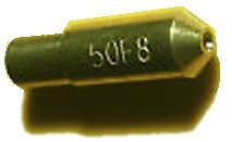
Figure 44. Idle Jet Identification (50F8)
Figure 45. DCOE Idle Jet Selection
Figure 46. DCOE Idle Jet Selection Arranged by
Inlet Area (approximately Richest at the Top)
The Idle Enrichment Screw:
The Idle Enrichment Screw controls the quantity of
mixed air and fuel at idle.
At idle, air is entering the engine at 5 locations (Fig. 47):
1. Around the throttle valve (that is just cracked open).
2. Through the air orifices in the Idle Jet.
3. Scavenged flow into the progression holes.
4. Through Idle Bypass Passage (if equipped).
5. Through holes drilled in throttle plate (if modified as in Fig. 48).
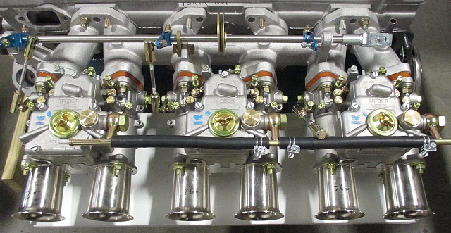
The Idle Enrichment Screw is located at the top of the carb next to the
intake manifold. There is one for each throat. They are visible in Figure 48.
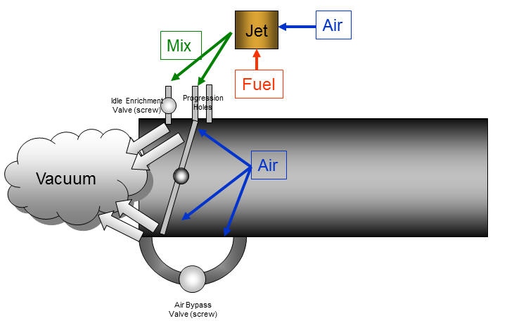
Figure 47. DCOE Air Flow at Idle.

Figure 48. Modified Throttle Plates with
Adjustable Sized Holes.
As mentioned above, the idle jet is first selected to obtain the optimal air/fuel
ratio when cruising. The Idle Enrichment Screw merely tweaks the air/fuel
ratio at idle.
Most Datsuns with Weber's idle best with Air/Fuel ratios of 14.7 or lower.
14.7 would be the cleanest with minimal fumes but at a slight sacrifice of
idle smoothness.
Early DCOE screws had a wide tapered end that flowed more mixture with just slight movements
(turns). Weber later changed DCOE's to a more precise screw with a very narrow taper.
The result is that early DCOE screws flowed adequate enrichment at ~ 1 turn out
from full stop. Later narrow tapered screws flowed the same amount at ~2.5
turns. Current production DCOE151's have the newer, narrower tapered screws.

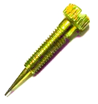
Figure 49. Idle Enrichment Screws (older, wider
taper on left, newer, narrower taper on right)
The Main Jet, Emulsion Tube, & Air Corrector:
The Main Jet is simply a precise orifice that controls
the quantity of fuel entering the main circuit. It snaps into the bottom of the
emulsion tube. The orifice sizes range from 0.80mm to 2.90mm. The size is
embossed on the jet in thousandths of mm.

Figure 50. DCOE Main Jet Size Selection Table.
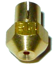


Figure 51. Main Jet (part, fitted, flow)
The Air Corrector is simply a precise orifice that
controls the quantity of air entering the main circuit. It snaps into the top of
the emulsion tube. The orifice sizes range from 0.80mm to 2.50mm. The size is
embossed on the corrector in thousandths of mm.
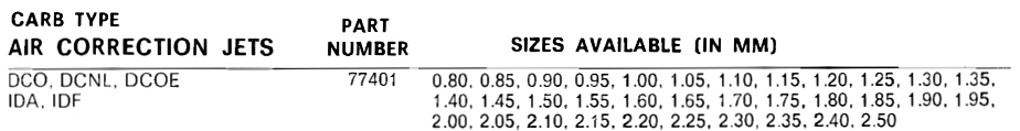
Figure 52. Air Corrector Selection
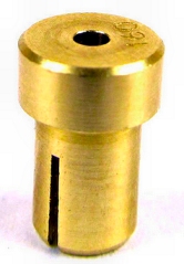

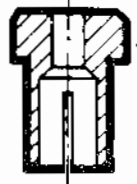
Figure 53. Air Corrector (part, fitted, diagram)
The Emulsion Tube is a complex part that comes in a variety shapes and sizes.
The Emulsion tubes vary by the outside diameter, steps in the outside diameter,
numbers of drillings, diameters of drillings, height of drillings and angle of
drillings.
Its purpose is to mix fuel and air during the acceleration phase from cruise to
WOT. The mixture results from air bubbling through the holes and then into the
fuel flow. The goal is to maintain an air fuel ratio of ~ 12 to 13 across the
acceleration rpm band.
Figure 54 shows the selection of emulsion tubes and typical applications.
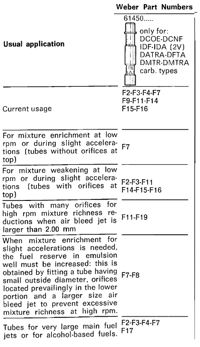
Figure 54. Emulsion Tube Selection
The Float, Needle Valve, & Fuel Strainer:
The fuel bowl is centered in the carb body
and feeds both throats.
It is filled through a needle valve. Needle Valves come with different orifice
diameters to cover a wide range of fuel consumptions.
Floats in the fuel bowel rise with the fuel level and close the needle valve
when the bowl is adequately filled. DCOE carbs should be mounted sideways to the
direction of travel so that side-to-side accelerations do not cause the float to
rise or fall (as the fuel sloshes). Fuel starvation at high rpms in a corner can
damage an engine.
The carb body should not be tilted more than 5 degrees when installed so as to prevent fuel leaking into the throat.
The various DCOE "fuel level" settings for different applications (cars) as
often listed in Weber books is to standardize the fuel level such that it
compensates for the tilt of the carb on that particular engine. The common
location for measuring fuel depth is in the emulsion tube well as its proper
functioning is dependent on this level. The typical value is 29mm down from the
top of the well casting. Beware that a commonly touted value of 25mm is often
found on the net but it is too high and leads to running far too rich at cruise
and causes fuel to slosh into the Venturi when the Main Circuit is not active.
Early DCOE floats are made of brass and are hollow. They can develop holes and
sink (causing incorrect fuel levels). Later floats are made from a synthetic
material and are not hollow.

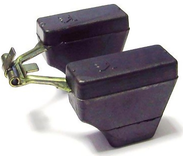
Figure 55. Early Brass Float and Later Synthetic
Float
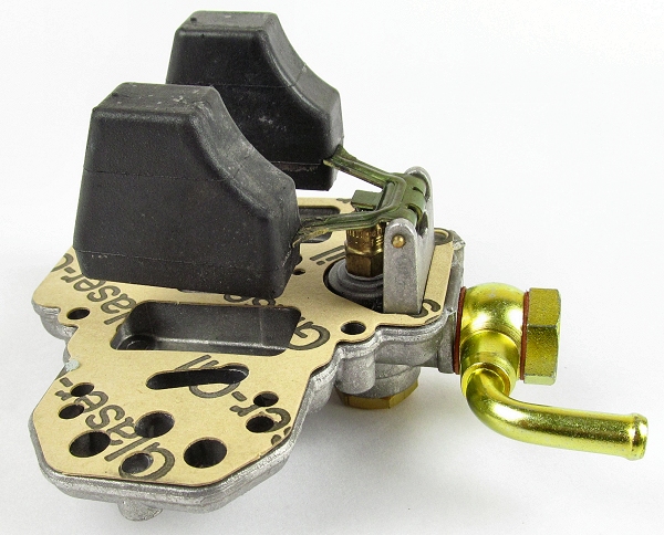
Figure 55. DCOE Lid (upside down) Showing Float,
Needle Valve, Gasket and Fuel Inlet
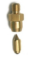
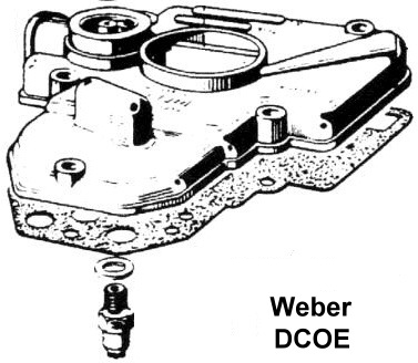
Figure 56. Needle Valve and DCOE Lid Showing
Needle Valve, Washer, and Gasket

Figure 57. Needle Valve and Washer (Measuring
height)
Important: Not all Needle Valves and Washers are the same height so this will
affect when the floats shut off the fuel and in turn, affect the fuel level.
Carefully measure fuel level in the Emulsion Tube Well every time the needle
valves are changed.
Figure 57a. DCOE/DCO Accelerator Pump Jet Selection
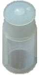
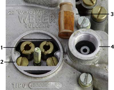
Figure 58. Fuel Strainer and DCOE Lid showing
Strainer (3) Location (4)
The Accelerator Pump & Jet:
The Accelerator Pump is much like an engine
cylinder. It has a piston, rod, and spring. The piston moves within a cylinder
filled with fuel. When operating, the spring pushes the piston which
squirts a column of gas. The whole assembly squirts in a
downward motion. The spring ensures every squirt is consistently pushed with the
same force. The rod comes in different lengths to vary the piston's sweep and
how much fuel is squirt. The
charge of fuel passes through several internal passages then through the pump jet.
The pump jet exit is on the roof of the throat just in front of the throttle
valve. It squirts over the top of the throttle valve. The size of the Pump Jet
Orifice effects the density of the fuel stream which is squirt and also
contributes to the duration.
As with nearly every other DCOE part, the accelerator pump's rod, spring, and jet
are all interchangeable with a wide selection of variations to make the carb
match the engine and application.

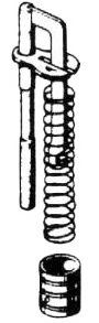
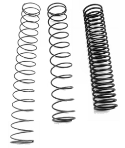
Figure 59. DCOE Accelerator Pump Parts and
Springs
The Accelerator Pump Jet has a very small aluminum washer fitted to ensure a correct fit. It sometimes is overlooked when replacing parts.
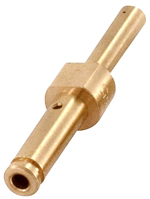
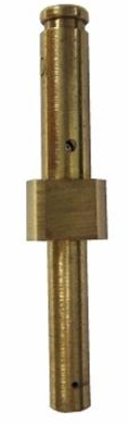
Figure 60. DCOE Accelerator Pump Jets and Washer
The Spill Jet, Weight, & Ball Valve:
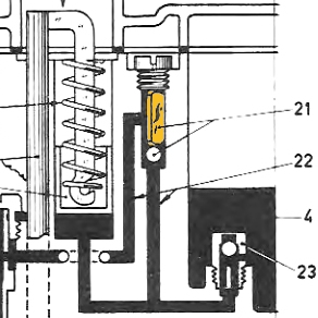
Figure 60a shows the details of the Accelerator Pump Circuit.
The Accelerator Pump Circuit contains additional parts to control when it
squirts fuel into the engine. The accelerator pump circuit is activated (by
lever #25 dropping) every time the accelerator pedal is pressed. It is desired
that circuit dispenses fuel on only on rapid pedal pressing but not on slow
pedal pressing. To facilitate this, the output from the pump piston can travel
two paths: 1. to the engine (fast press through #24), 2. back to the fuel bowl
(slow press through #23). Path to the engine has a vertical passage blocked at
the bottom by a ball (#21)with a weight on top (#22). The path to the fuel bowl
also has a ball valve in a jet (#23) where the fuel returns back to the bowl
(through side of this jet).
A fast press of the accelerator pedal drops lever #25 allowing spring #28 to
push the piston #26 down. The piston pushes fuel from its chamber towards the
ball valve #21 and towards the ball valve #23 (Spill Jet). The pressure of the
push forces the ball valve and weight #21 upward. This opens the passage and
allows the pressurized charge of fuel to continue on to the Accelerator Pump Jet
#24 then out into the engine via the carb throat. The piston also pushes fuel
towards the spill jet #23. The ball in the spill jet is forced upward however it
closes off the top which is the main passage from the fuel bowl #4. This closing
off prevents the piston from pushing fuel back into the fuel bowl so that the
charge goes to the engine. The spill jet has a small hole in the side below the
ball valve thus a small amount of the charge does leak back into the bowl.
A slow press of the accelerator pedal prevents the spring #28 from pushing the
piston #26 quickly. The pressurized charge lacks the sudden impulse of the
spring and is not sufficient to raise the weight and open the valve #21. The
pressurized charge is also not sufficient to raise the ball and close the spill
jet #23, so the fuel is returned back to the fuel bowl through #23.
Fast presses squirt fuel into the engine. Slow presses simply bleed fuel back to
the fuel bowl.
As with all other circuits, the Accelerator Pump Circuit can be matched to the
engine by varying the components. A selection of spill jet bleed back holes and
pump jets are available.
Figure 60a. DCOE Accelerator Pump Circuit

Figure 61. DCOE Spill Jet

Figure 62. DCOE Accelerator Pump Circuit Weights and Ball Valve

Figure 63. DCOE Accelerator Pump Jet Selection
The Throttle Plate:
DCOE throttle plates come in a few variations. They can be used to move the location in
the throat where they come to a close. This relocation can be used to
rehabilitate a carb whose aluminum throat is worn from usage at its original
stop. Altering the throttle plate's stop location also changes distance before
the progression circuit engages. This change may require additional tuning to
compensate.
Some early 40DCOE's came with 78.5°
plates. 42DCOE's had 82°.
40DCOE 78.0° part: 64005.044
40mm 78.0° part: 64005.087
40mm 78.0° part: 64005.126
40DCOE 78.5° part: 64005.059
45DCOE 78.0° part: 64005.084
50DCOE .0° part: 64005.135
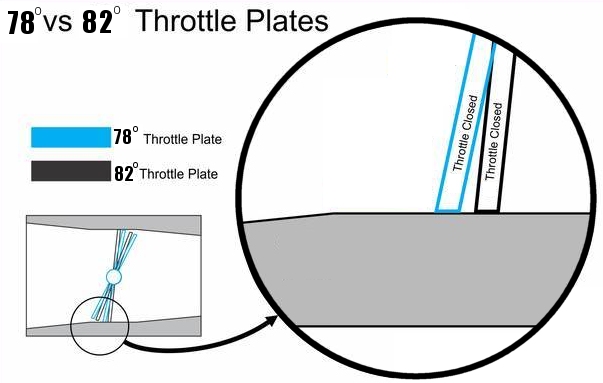
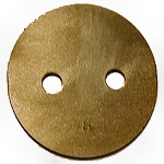
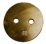
Figure 64. DCOE Throttle Plates 78° and 82°
5. Tuning
(TBD)
This section is specific to tuning Triple Weber DCOE Side Draft Carburetors on
the Datsun 240z, 260z & 280z. The principals will apply to other applications.
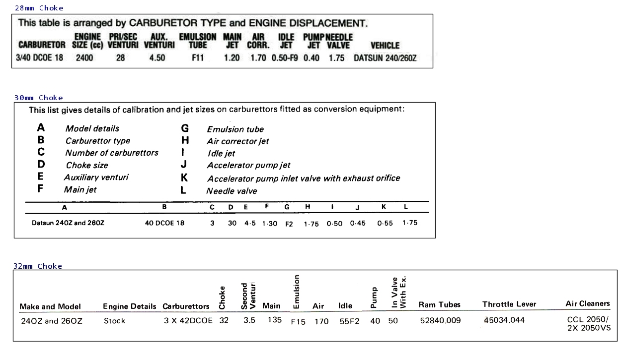
Here are the default settings for DCOE's on 240z's & 260z's that are published
in books. These may be useful starting points for some (note the rare and
expensive 42DCOE):
1. Selection of DCOE Type
Linkage
Timing
Heat Shielding
Valve Adjustment
1. plug inlet jet/ball valve leak back to accel.
circuit at bottom of fuel bowl with bolt.
2. set throttle linkage so that valves are covering
the first progression hole.
3. remove main jets.
4. experiment at low rpms and tune the idle circuit
for idle and low rpm operation (carefully drive around to do this and measure
a/f)
5. install the mains and tune for high rpm and WOT
performance
6. balance a/f at cruise at 60mph and 70mph and at idle
6. install the accelerator circuit jet/ball valve AND
add springs to press the weights down OR replace the weights with springs.
7. adjust the accelerator circuit for fast
RPM transitions
6. Rebuilding
TBD

7. Modifications
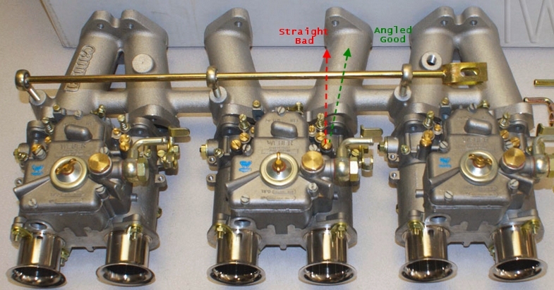
Accelerator Jets:
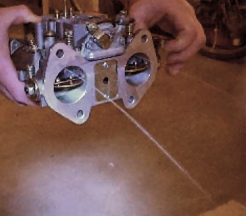
1. Align the "squirt" with the manifold:
File flat section of the accelerator
jet so that it can be clocked such that the "squirt" shoots in the centre of the
manifold runner. This problem arises because the default shot is straight out
the back of the DCOE however, the 240z,260z & 280z manifold runners are angled towards the input
ports on the head.
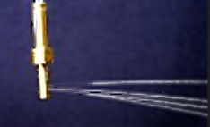
2. Disperse the Spray:
Drill more holes in the accelerator jet to reduce the large liquid squirt
into a finer misting spray. (Part is available in Japan)

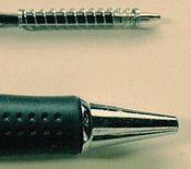
3. Stop Leaking:
Install springs to replace the weights. This will prevent the the accelerator
circuit from leaking due to road vibrations lifting the weight. Springs can be
sourced from pens.
Auxiliary Venturi:
1. Reduce Obstructions:
Remove the structural post side of cross-member so that the Aux. Venturi is
only supported from one side (like Dellorto below).

2. Refine Airfoil:
Shape the leading and trailing edges to reduce manufacturing imperfections
and to improve flow.
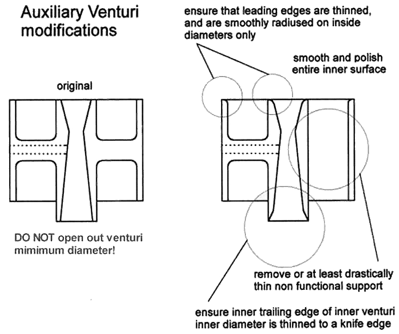
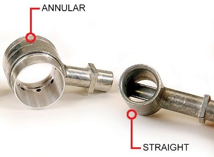
3. Improve Aux. Venturi Type:
Replace Aux. Venturi with Annular Discharge Ring insert (like on Holley Carbs).
4. Improve High Rpm Atomization
Slot the upstream and down stream Venturi Tube:

Throttle Valve Shaft:
1. Reduce the cross-sectional blockage:
It is not recommended to thin the throttle valve shaft
(It is already done). Simply countersinking flat-top screws and trimming the
protrusion is all that is needed.


Throttle Plate:
1. Balance Throats at Idle:
For non-40DCOE151 carbs, drill holes in the throttle plate to balance the
idle air between the two throats in a carb. Solder shut if you drill too big.
Below is an extreme adjustable example.

Throttle Plate Return Spring:
1. Improve Throttle Plate Closing (40DCOE):
Install a stronger spring to consistently return the throttle plates to a
fully closed position. This stabilizes idle.
Weber Part No: 47605.012 Normal (Weakest)
Weber Part No: 47605.027 Stronger
Weber Part No: 47605.009 Strongest
Intake Port:
1. Install stubby elliptical shaped air horns that have full radius to the back.

Linkage:
1. Improve Mechanical Precision of Linkage:
Replace conventional rods with adjustable rods.
TBD
Manifold Heat:
1. Increase heat into manifold:
A hot intake manifold will quickly evaporate liquid fuel. Capture heat from head
and from exhaust below.
Carb Insulation:
1. Thermally Insulate the carb:
Insulate the carbs from the intake manifold's heat and from the exhaust header's
heat so they remains cool. A lower heat shield and ducting air from the front of the engine bay helps
to cool the carbs.
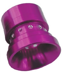
Annular Ring Venturi:
1. Replace the Aux. Venturi and Main Venturi with a single Annular Ring Venturi:
Install a "Giant Holley Booster" in the throat of the carb.
Progression Holes:
1. Drill more progression holes to change progression behaviour.
Notes:
This is for information only. This modification is a
drastic last step and is generally not needed to make DCOE carbs work on a Z.
All jet variations, emulsion tube variations, choke sizes, aux Venturi sizes and
fuel levels should be explored before drilling more holes.
This modification requires accurate hole placement so a drill or milling machine
with precise x/y table is needed.
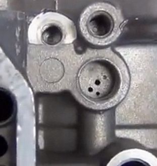
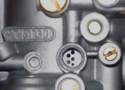
Some 45DCOE carbs have 2 holes, some have 4 holes, most have 3 as well as most
40DCOE's have 3 holes. FYI many Dellorto's have 5.
Here is an example of a 45DCOE152 (3 hole to 4 hole)) drilling template:
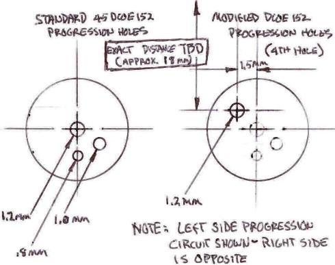
Here is a 45DCOE15 (2 holes) and a 45DCOE152G (4 holes) and Dellorto (5 holes):

8. Racing
1. When towing or transporting a car with Weber
carbs, a dry fuel bowl will allow the float to bounce and jump with every
vibration and pothole in the road. A rubber-tipped needle valve will reduce
wear and tear.
2. Some racers remove and replace the internal
throttle return spring with an external spring as the internal spring may
break resulting in a stuck-open throttle which may cause a fatal crash.
However this modification causes another risk: The locking pin of the
accelerator pump cam can slip away and block the throttle in an OPEN
position because by removing the internal spring, it removes the force on
the locking pin which holds it tight. Without this force the pump cam may
vibrate from engine and road vibrations which will eventually destroy the
pin. In fact it is much more dangerous to remove internal spring then keep
it in place. If someone would like to remove internal spring, then also
remove the pump cam pin and replace it with stainless wire of appropriate
diameter, leave it longer than the pin, and bend it on both ends.
9. Documents
Borg Warner:

-
"Weber
Carburettors A Guide to Tuning"
Centerline:
-
"Set Fuel
Level 29mm"
Hammil:
-
"How to Build and Power Tune Weber DCOE Carburettors" (Text for searching)
-
"How to Build and Power Tune Weber DCOE Carburettors" (Grey Scale Images)
-
"How to Build and Power Tune Weber DCOE Carburettors" (Colour
Excerpts)
Inglese
- "V8 Manifold"
Passini:
-
Excerpts
from "Weber Carburettors Tuning Tips And Techniques, John Passini"
WebCon:
-
"Starter Circuit
Block"
Weber:

-
"Weber Tuning
Manual"
-
"Weber DCOE
Service Manual"